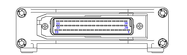
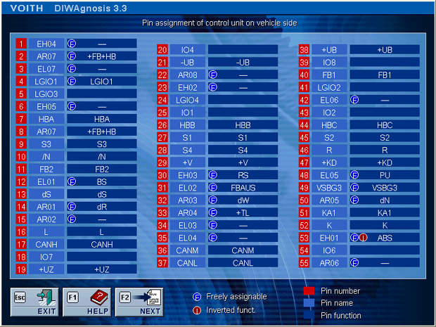
The above picture shows the pin assignment of the control unit on vehicle side. The pin designation is indicated to the right of the pin number [red]. The function assigned to this particular pin is depicted next to it.
Variable inputs allow their function to be selected via the data record, i.e. the data record specifies which function is activated at which pin.
The control unit features inputs for switches that can be connected to ground (ELxx) and to +24 V (EHxx).
For a switch to ground, the signal is usually active if a ground signal is on, and inactive if the input is open. This behaviour can be programmed in the data record of the control unit.
This behaviour can be inverted via settings in the data record.
For control units with serial numbers higher than 837.
Apply menu item A "Read identification and pin assignment" to display a table of the current connector pin assignment of vehicle and transmission as specified in the record.
Unlike the screen of DIWAgnosis, which shows the vehicle-specific pin assignment at the variable inputs and outputs, the following table presents the possible pin assignment. The vehicle-specific pin assignment is defined together with the vehicle manufacturer in the development phase and implemented in the data record.
| Signal | Pin | Explanation |
| +UZ | 19 | Positive supply voltage to E200 control unit |
| +UB | 38 | Positive supply voltage to solenoid valves |
| -UB | 21 | Ground connection for control unit, sensors and solenoid valves |
| LGIO2 | 41 | Load transmitter connection: PWM or voltage signal / USA: Oil level float switch
Terminal A at J1587 |
| LGIO3 | 5 | Load transmitter connection: PWM or ground / USA: Speed signal output |
| LGIO4 | 24 | Load transmitter connection: PWM or supply voltage
Terminal B at J1587 |
| VSBG1 | 40 | Input signal for foot brake pedal - position 1 |
| VSBG2 | 11 | Input signal for foot brake pedal - position 2 |
| VSBG3 | 49 | Input signal for foot brake pedal - position 3 / WABCO analog signal FBM |
| HB1 | 7 | Input signal for hand brake lever - position 1 |
| HB2 | 26 | Input signal for hand brake lever - position 2 |
| HB3 | 44 | Input signal for hand brake lever - position 3 |
| S1 | 27 | Input for [1] button of gear selector switch |
| S2 | 45 | Input for [2] button of gear selector switch |
| S3 | 9 | Input for [3] button of gear selector switch |
| S4 | 28 | Input for [D] button of gear selector switch |
| /N | 10 | Redundancy signal for depressed button of gear selector switch |
| R | 46 | Input for [R] button of gear selector switch |
| VRUZ | 29 | Supply voltage for gear selector switch |
| KDUZ | 47 | Supply voltage to kick-down, max. 100mA |
| EH01 | 53 | Variable input for switch to +UB |
| EH02 | 23 | Variable input for switch to +UB |
| EH03 | 30 | Variable input for switch to +UB |
| EH04 | 1 | Variable input for switch to +UB |
| EH05 | 6 | Variable input for switch to +UB |
| EL01 | 12 | Variable input for switch to -UB |
| EL02 | 31 | Variable input for switch to -UB |
| EL03 | 34 | Variable input for switch to -UB |
| EL04 | 35 | Variable input for switch to -UB |
| EL05 | 48 | Variable input for switch to -UB |
| EL06 | 42 | Variable input for switch to -UB |
| EL07 | 3 | Variable input for switch to -UB |
| LGIO1 | 4 | Kick-down signal of the different load transmitter types |
| KA1 | 51 | Digital output, plus switched, standard: Activates the central warning light (ZW) |
| AR01 | 14 | Digital output, plus switched |
| AR02 | 15 | Digital output, plus switched |
| AR03 | 32 | Digital output, plus switched |
| AR04 | 33 | Digital output, plus switched |
| AR05 | 50 | Digital output, plus switched |
| AR06 | 55 | Digital output, plus switched |
| AR07 | 2/8 | Digital output, plus switched |
| AR08 | 22 | Digital output, ground switched |
| dS | 13 | Digital output to control safety relay This relay is crucial to the reliable function of the control unit; its replacement, e.g. by a PLC, must be tested in the particular case. |
| K | 52 | Serial port for diagnosis |
| L | 16 | Serial port for diagnosis |
| CANH | 17 | CAN-high according to SAE J1939 / IES standard |
| CANL | 37 | CAN-low according to SAE J1939 / IES standard |
| CANM | 36 | CAN-ground |