
Description 
| Display active inputs |
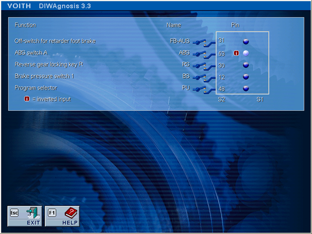
Digital inputs on the vehicle side The digital inputs activated in the dataset are displayed here. Up to twelve functions are available depending on the settings in the dataset. Assignment of the digital inputs in the vehicle is variable, i.e. the functions can be active at different input pins in the control unit, depending on the settings in the dataset. Low-side or high-side input levels The control unit features inputs for switches to ground (ELxx) and switches to +24 V (EHxx). For a switch to ground the signal is usually active if a ground signal is on, and inactive if a +24V signal is present or the input is open. This behaviour can be changed (inverted) via settings in the control unit's dataset. In this case, the signal is active for the control unit if +24V is present or if the input remains open, and it is inactive if a ground signal is connected. The situation is vice versa for +24V (EHxx) switches.
The condition (active or inactive) of the input is displayed by LEDs. The input for the control unit is active if the LED is lit and the signal is inactive if it is not lit. However, as explained above, this does not give any indication of the physical state of the input, i.e. whether it is connected to +24V or to ground. - LED lit -> signal is active
- LED not lit > signal is inactive
Explanation of the displayed input switches | Signal | Description | | FBAUS | Foot brake on/off switch The converter brake can no longer be started using the foot brake pedal if this signal is activated. This input is used in vehicles without ABS if the response of the converter brake is too abrupt in winter. | | ABS | An active ABS signal prevents activation of the converter brake or terminates converter brake action. | | RS | Reverse gear locking button | | BS | Brake pressure switch 1 – Brake pressure is between
p = 0.5 – 1 bar | | ABSICH | Brake pressure switch 2 – Brake pressure is between
p = 1 – 3 bar When cabling the brake pressure switch, make sure that the BS brake pressure switch is activated before brake pressure switch BS2 when applying the brake pedal. | | PU | This input can be used for switching between two shift programs when the program changeover switch PU is activated. | | OELS | Oil level float switch – Oil level check | | HSB | Bus stop brake | | SICCA | Additional gear activation lock | | ANS | Automatic neutral at standstill | | SHSB | Special protection of bus stop brake | | |
Table: Pin number allocations for variable inputs
- Connector on vehicle side
| High-side input | EH01 | EH02 | EH03 | EH04 | EH05 | | | | Pin number at S2 | 53 | 23 | 30 | 1 | 6 | | |
| Low-side input | EL01 | EL02 | EL03 | EL04 | EL05 | EL06 | EL07 | | Pin number at S2 | 12 | 31 | 34 | 35 | 48 | 42 | 3 |
- Connector on transmission side
| Low-side input | EL08 | EL09 | | Pin number at S1 | 4 | 40 |
Terminal Connection Diagram 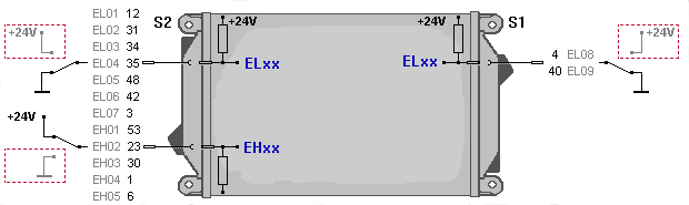
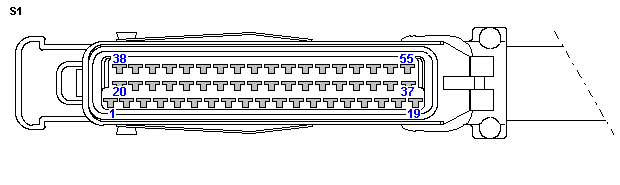
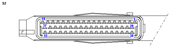
| 


