
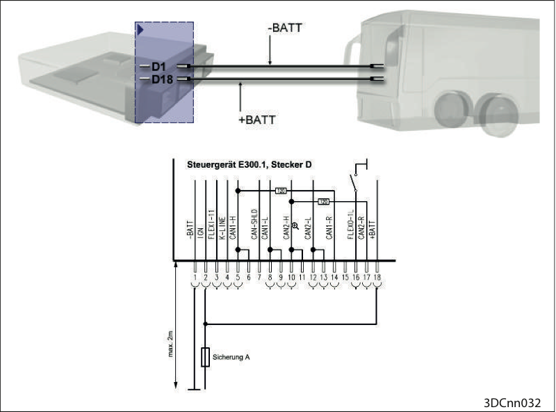
Check voltage at controller
Check the voltage at connector D of the transmission controller as follows:
between PIN1 (-Batt) and PIN2 (IGN) and
between PIN1 (-Batt) and PIN18 (+Batt)
+Batt and IGN can be protected by one fuse each or jointly by one fuse See associated vehicle circuit diagram. |  |
Described in the workshop manual Hall sensor only for DIWA.5, as checking is only possible with ALADIN.
Transmission oil temperature sensor

Terminal assignment
Pin assignment of transmission oil temperature sensor
1 = connection to ground
2 = supply connection
ATTENTION: | |
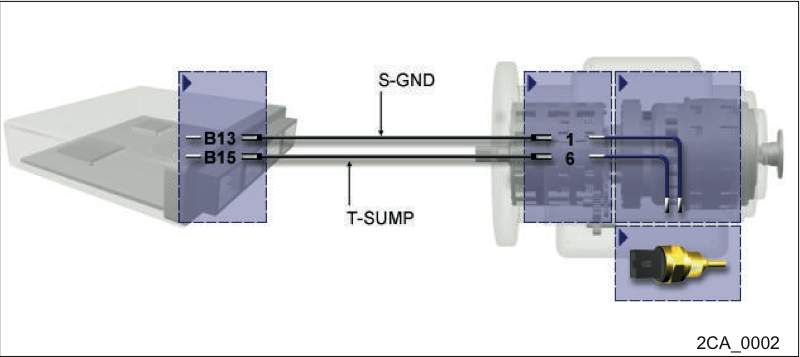
Terminal assignment
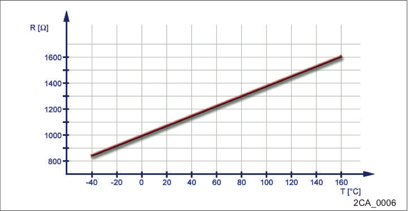
Characteristic curve
Remove the oil pan.
Check plug connections and cables.
Disconnect the plug connection on the temperature sensor.
Check that the inside of the sensor is undamaged:
When measuring the resistance, please observe the dependence on the temperature.
Simultaneously to the resistance measurement, the temperature of the sensor has to be measured, too, or estimated with utmost accuracy. Read the nominal resistance from the temperature curve below and compare it to the measured or estimated temperature.
Measure the resistance of the sensor between pin 1 and pin 2.
The sensor works correctly if the measured resistance deviates from the nominal resistance by no more than ± 50 ohms.
It is important that resistance is not measurable between the pins and the sensor housing; the resistance is infinitely large.
The combined temperature & oil level sensor is installed in version E300.1 of the transmission controller.
The integrated temperature sensor is a Pt 1000 element (platinum, 1000 ohms at 0°C). It has the same features as the temperature sensor for the converter.
The oil enters through the lower openings, air can escape through the upper openings. The channel duct is optimized so that flows outside the sensor do not cause fluctuations of the oil level in the sensor.
A wire inside the sensor is briefly heated up by a constant current. The oil level is determined via the electrical resistance of the wire. By the cooling of the wire through the oil, conclusions can be drawn as to the oil level.
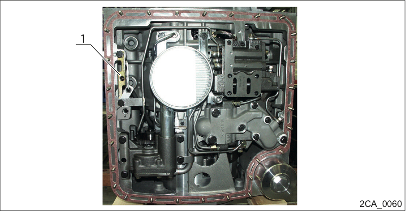
The short side of the sensor faces in the direction of the oil sump (below).
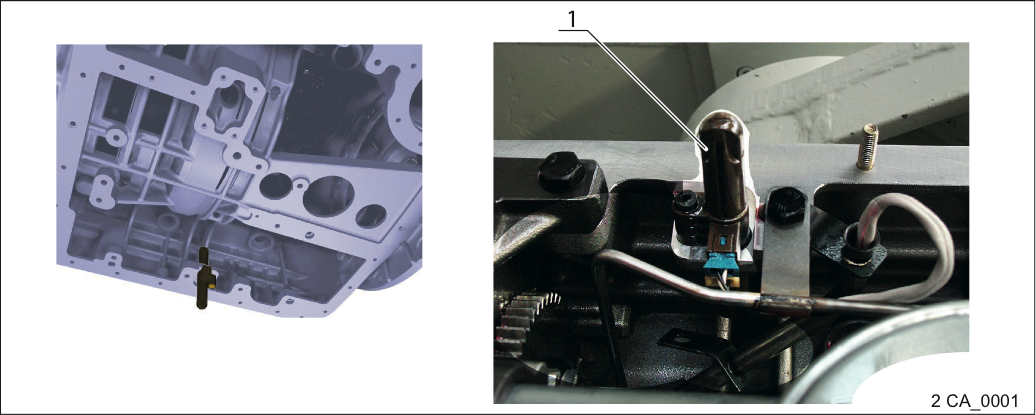
Position of the temperature/oil level sensor
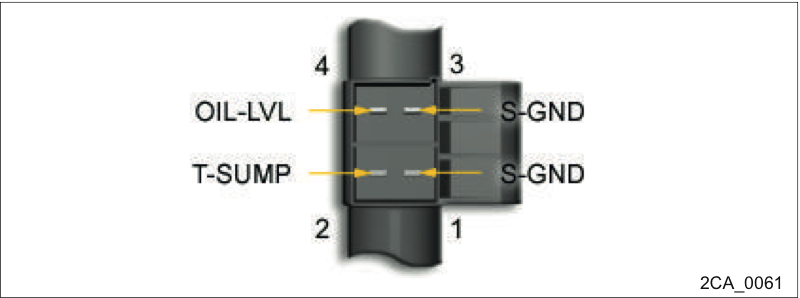
Terminal assignment sensor
Sensor | Connectors | Description |
|---|---|---|
3 4 1 2 | 1 2 1 2 | S-GND = sensor ground - oil level OIL-LVL = oil level signal S-GND = sensor ground - temperature T-SUMP = temperature signal |
The polarity of signal and ground is irrelevant for the correct function.
The sensor function can be checked using a resistance meter. It is important that the dependence of the resistance on the sensor temperature is observed!
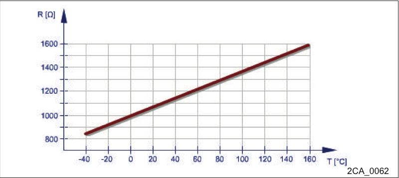
Temperature sensor check
Measure the resistance of the sensor between pin 1 at the bottom (S-GND) and pin 2 (T-SUMP).
Measure the sensor temperature or estimate it as exactly as possible.
Read the desired resistance from the displayed temperature curve and compare it with the measured value.
The sensor works correctly if the measured resistance deviates from the nominal resistance by no more than ± 50 ohms.
The sensor function can be checked using a resistance meter. The sensor resistance depends on the temperature!
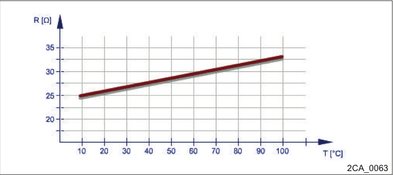
Oil level sensor check
Measure the resistance of the sensor between pin 1 at the top (S-GND) and pin 2 at the top (OIL-LVL).
Measure the sensor temperature or estimate it as exactly as possible.
Read the desired resistance from the displayed temperature curve and compare it with the measured value.
The sensor works correctly if the measured resistance deviates from the nominal resistance by no more than ± 5 ohms.
Check connectors, plug-in contacts, connector connections and cabling.
Check the connectors and their contacts for firm seating, interruption, short circuit, cable breakage and corrosion. The following chapters may be helpful:
Troubleshooting a short-circuit to ground→ Troubleshooting a short-circuit to ground
Troubleshooting for short-circuit to 24 volts→ Troubleshooting for short-circuit to 24 volts
Troubleshooting a short-circuit of two signals → Troubleshooting a short-circuit of two signals.
Troubleshooting for cable breakage → Troubleshooting for cable break
Possibly check pin assignment according to circuit diagram and measure contact resistances.
There may be several reasons why a short-circuit to ground is detected for a signal:
The signal line has contact to the chassis or to other elements linked to the battery ground
The signal line has contact to a ground cable (e.g. in the cable harness)
An electrical component is internally defective (e.g. switching contact is jammed)

Contact of cable to ground
Short-circuits can occur in different places, for instance:
in plug connections due to warped contacts
at vibrating parts
in places where there is a lot of cable movement, e.g. in the joint of an articulation bus
where the cable passes close to sharp-edged parts
by foreign bodies inside plug connections or cables, e.g. dirt, moisture...
inside the transmission controller
Turn the ignition off.
Pull connector that carries the faulted signal out of the transmission controller and check contacts.
Use a multimeter set to resistance mode to check whether the short-circuit in the cable is still present.
Refer to circuit diagram to find out whether the short-circuit may have been caused by a connected electrical component. The fault possibilities are thus narrowed down.
If the electrical component is intact, disconnect all electrical components from the cable. Measure resistance between the signal line and
all ground lines
battery ground and ground contact at transmission controller
measure all other lines at unplugged connector.
Note the number of contacts at which a resistance value was measured that does not comply with the correct value.
Disconnect one after the other all connectors on which the faulted signal is present, check contacts.
Measure into each opened connection with the multimeter before disconnecting the next plug connection and track the short-circuit to the connecting point of the electrical component (e.g. kickdown switch).
If the measured value is correct, the short-circuit is located in the previous line section.
Recheck all contacts of the faulted line segment and look for defective spots.
If the fault cannot be localized, there may be a loose contact. The fault may be reproduced by shaking at the cables.
If abrasions, cable breaks, defective contacts or other defects have been detected, replace the affected cable or the electrical component.
Eliminate the defect causing the problem.
If you are certain that the short-circuit is not located outside the transmission controller, replace the controller with another one and check whether the fault has been eliminated.
If the fault has been eliminated due to the reproducibility of the fault, reinstall the original transmission controller.
If the fault recurs, the transmission controller is probably defective.
Order a controller with the same item number and install it in the vehicle.
There may be a number of reasons why a short-circuit to 24 V is detected for a signal:
The signal line has contact to a line conducting 24 V (e.g. in the cable harness).
An electrical component is internally defective (e.g. switching contact is jammed)

Contact of the cable with 24 volts
Short-circuits can occur in different places, for instance:
in plug connections due to warped contacts
at vibrating parts
in places where there is a lot of cable movement, e.g. in the joint of an articulation bus
where the cable passes close to sharp-edged parts
by foreign bodies inside plug connections or cables, e.g. dirt, moisture...
inside the transmission controller
Turn the ignition off.
Pull connector that carries the faulted signal out of the transmission controller and check contacts.
Use a multimeter set to resistance mode to check whether the short-circuit in the cable is still present.
Refer to circuit diagram to find out whether the short-circuit may have been caused by a connected electrical component. The fault possibilities are thus narrowed down.
If the electrical component is intact, disconnect all electrical components from the cable. Measure resistance between the signal line and
all lines conducting 24 volts
positive pole of battery
supply voltage of the transmission controller
measure all other lines at unplugged connector
Note the number of contacts at which a resistance value was measured that does not comply with the correct value.
Disconnect one after the other all connectors on which the faulted signal is present, check contacts.
Measure into each opened connection with the multimeter before disconnecting the next plug connection and track the short-circuit to the connecting point of the electrical component (e.g. kickdown switch).
If the measured value is correct, the short-circuit is located in the previous line section.
Recheck all contacts of the faulted line segment and look for defective spots.
If the fault cannot be localized, there may be a loose contact. The fault may be reproduced by shaking at the cables.
If abrasions, cable breaks, defective contacts or other defects have been detected, replace the affected cable or the electrical component.
Eliminate the defect causing the problem.
If you are certain that the short-circuit is not located outside the transmission controller, replace the controller with another one and check whether the fault has been eliminated.
If the fault has been eliminated due to the reproducibility of the fault, reinstall the original transmission controller.
If the fault recurs, the transmission controller is probably defective.
Order a controller with the same item number and install it in the vehicle.
If a signal is short-circuited to another signal, the cause is in most cases an abrasion or several mutually touching pins in a plug connection.

Contact of the cable with another cable
Short-circuits can occur in different places, for instance:
in plug connections due to warped contacts
at vibrating parts
in places where there is a lot of cable movement, e.g. in the joint of an articulation bus
where the cable passes close to sharp-edged parts
by foreign bodies inside plug connections or cables, e.g. dirt, moisture...
inside the transmission controller
Turn the ignition off.
Pull connector that carries the faulted signal out of the transmission controller and check contacts.
Use a multimeter set to resistance mode to check whether the short-circuit in the cable is still present. Accordingly, check resistance between the affected signal line and all other lines.
Refer to wiring diagram to find out whether the short-circuit may have been caused by a connected electrical component. The fault possibilities are thus narrowed down.
If the electrical component is intact, disconnect all electrical components from the cable. Accordingly, recheck resistance between the affected signal line and all other lines.
Check number of contacts that are short-circuited to each other. Disconnect one after the other all connectors on which the faulted signals are present, check contacts.
Measure with the multimeter into each opened connection before disconnecting the next plug connection.
If the measured value is correct, the short-circuit is located in the previous line section.
Recheck all contacts of the faulted line segment and look for defective spots.
If the fault cannot be localized, there may be a loose contact. The fault may be reproduced by shaking at the cables.
If abrasions, cable breaks, defective contacts or other defects have been detected, replace the affected cable or the electrical component.
Eliminate the defect causing the problem.
If you are certain that the short-circuit is not located outside the transmission controller, replace the controller with another one and check whether the fault has been eliminated.
If the fault has been eliminated due to the reproducibility of the fault, reinstall the original transmission controller.
If the fault recurs, the transmission controller is probably defective.
Order a controller with the same item number and install it in the vehicle.
A defective electrical component may be displayed as cable break (loose contact, jammed switching contact or too high line resistance).

Cable break
Cable breaks can occur in different places, for instance:
at crimpings and plug-in contacts
at vibrating parts
in places where there is a lot of cable movement, e.g. in the joint of an articulation bus
where the cable passes close to sharp-edged parts
inside the transmission controller
Turn the ignition off.
Pull connector on which the interrupted signal applies out of the transmission controller and check contacts.
Refer to wiring diagram to find out whether the interruption may be caused by a connected electrical component. The fault possibilities are thus narrowed down.
If the electrical component is intact, insert a cable jumper at this end of the cable connection between the signal line and the return line required for the signal.
Use a multimeter set to resistance mode to measure between the signal line and the corresponding return line whether a cable break exists.
Disconnect one after the other all connectors on which the affected signal is present, check contacts.
Measure into each opened connection with the multimeter before disconnecting the next plug connection and track the cable break to the connecting point of the electrical component.
If the measured value is correct, the cable break is located in the previous line section.
Recheck all contacts of the faulted line segment and find defective spots.
If the fault cannot be localized, there may be a loose contact. The fault may be reproduced by shaking at the cables.
If abrasions, cable breaks, defective contacts or other defects have been detected, replace the affected cable or the electrical component.
Eliminate the defect causing the problem.
If you are certain that the interruption is not located outside the transmission controller, replace the controller and check whether the fault has been eliminated.
If the fault has been eliminated due to the reproducibility of the fault, reinstall the original transmission controller.
If the fault recurs, the transmission controller is probably defective.
Order a controller with the same item number and install it in the vehicle.
NOTICE
Damage to the transmission controller due to overvoltage!
Turn the ignition off prior to installation or removal.
Never expose the on-board electrical wiring to higher voltages than 45 V.
Do not touch any contacts to avoid ESD (electrostatic discharging) and soiling
Dismantle/replace the controller and send it to the Voith Customer Service for inspection.
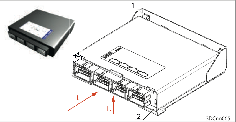
Dismantle the controller
Unplug connectors A, B, C, D (connector secured by "lug", lift "lug")
Press the device backwards (I.) against the springs (1).
List the device out of the rail (2) upwards (II.).
Pull out the device.