
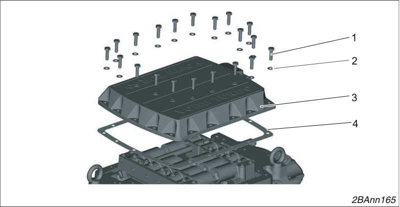
Removing the one-piece control block cover
Loosen 20 screws (1) and remove them with their washers (2).
Remove the cover (3).
Remove the seal (4).
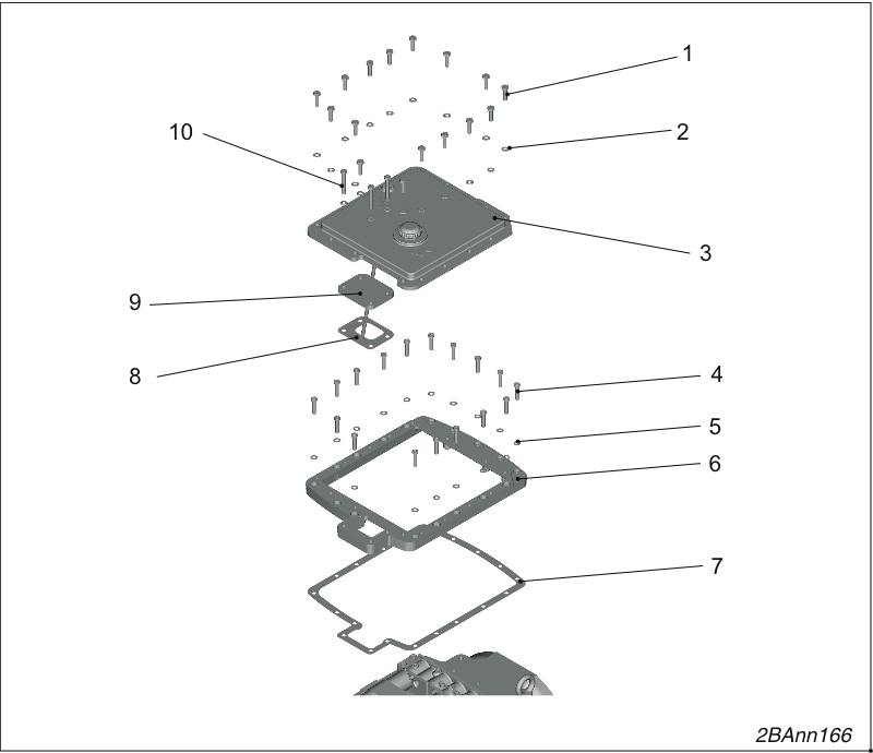
Remove the two-piece control block cover.
Loosen 13 screws (1) and remove them with their washers (2).
Remove the cover (3).
Remove the cover (9).
Remove the seal (8).
Loosen 13 screws (4) and remove them with their washers (5).
Remove the frame (6).
Remove the seal (7).
Installing the control block cover
Insert the new seal (4).
The seal must be free of grease when you install it.
Screw the control block cover (3) tight using 20 hexagon bolts M8 x 30 - 8.8 (1) and washers B 8.4 (2).
Tightening torque 23 Nm.
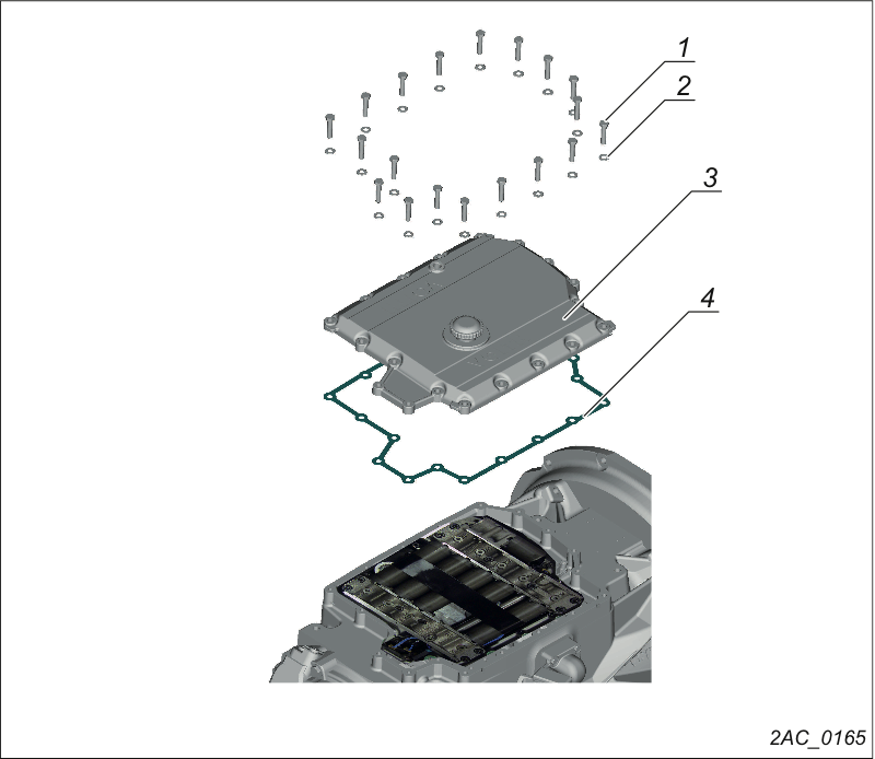
Removing the control block cover
Loosen 20 bolts (1) and remove them with 20 washers (2).
Remove the control block cover (3).
Remove the seal (4).
Installing the control block cover
Insert the new seal (4).
The seal must be free of grease when you install it.
Screw the control block cover (3) tight using 20 hexagon bolts M8 x 30 - 8.8 (1) and washers B 8.4 (2).
Tightening torque 23 Nm.
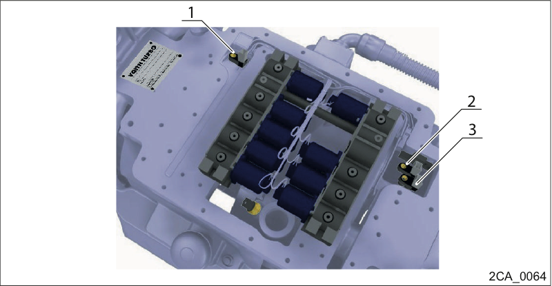
Position of the DIWA.5 speed sensors
1. N1 input speed (engine speed)
2. N3 turbine crown gear speed
3. N2 output speed
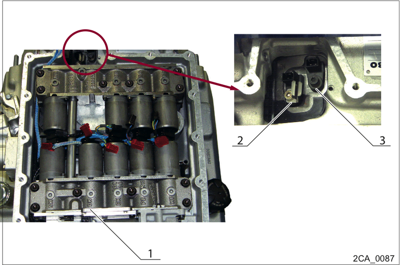
Position of the DIWA.6 speed sensors
1. N1 input speed (engine speed)
2. N3 turbine crown gear speed
3. N2 output speed
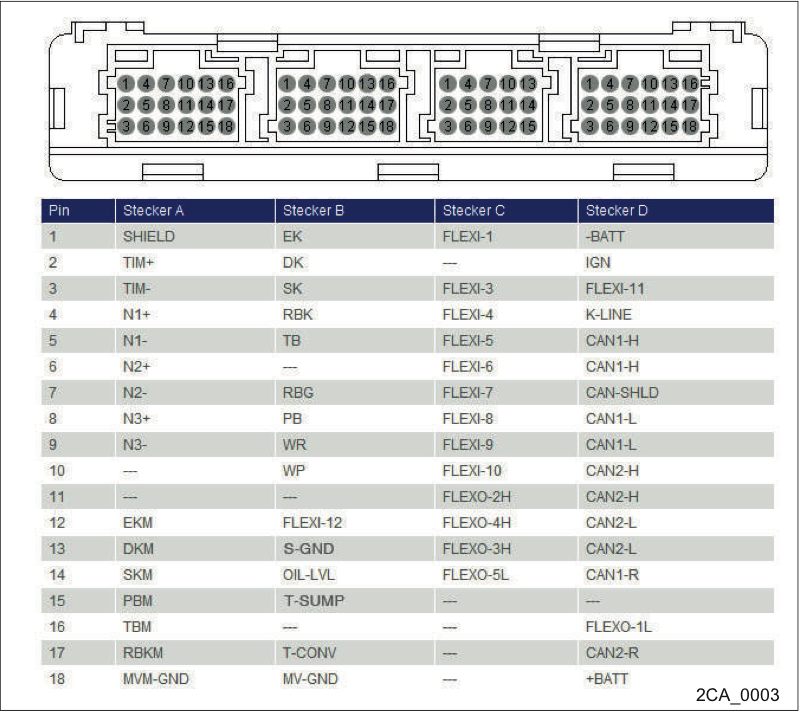
Pin assignment of transmission controller
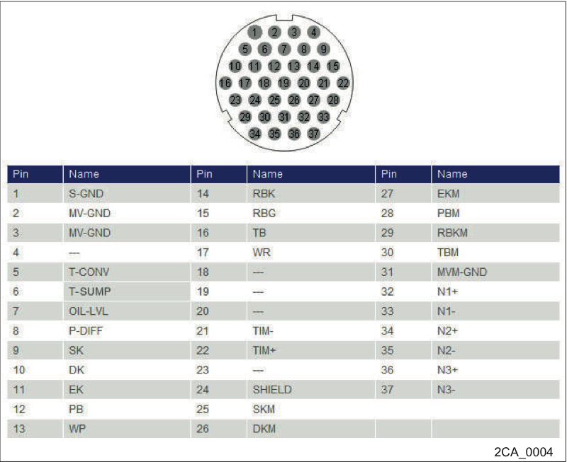
Pin assignment of transmission connector
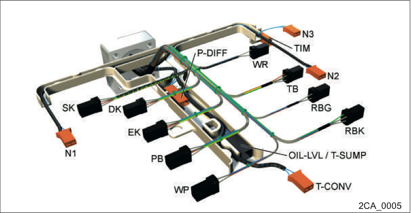
Internal cable harness
Check connectors, plug-in contacts, connector connections and cabling.
Check the connectors and their contacts for firm seating, interruption, short circuit, cable breakage and corrosion. The following chapters may be helpful:
Troubleshooting a short-circuit to ground→ Troubleshooting a short-circuit to ground
Troubleshooting for short-circuit to 24 volts→ Troubleshooting for short-circuit to 24 volts
Troubleshooting a short-circuit of two signals → Troubleshooting a short-circuit of two signals.
Troubleshooting for cable breakage → Troubleshooting for cable break
Possibly check pin assignment according to circuit diagram and measure contact resistances.
There may be several reasons why a short-circuit to ground is detected for a signal:
The signal line has contact to the chassis or to other elements linked to the battery ground
The signal line has contact to a ground cable (e.g. in the cable harness)
An electrical component is internally defective (e.g. switching contact is jammed)

Contact of cable to ground
Short-circuits can occur in different places, for instance:
in plug connections due to warped contacts
at vibrating parts
in places where there is a lot of cable movement, e.g. in the joint of an articulation bus
where the cable passes close to sharp-edged parts
by foreign bodies inside plug connections or cables, e.g. dirt, moisture...
inside the transmission controller
Turn the ignition off.
Pull connector that carries the faulted signal out of the transmission controller and check contacts.
Use a multimeter set to resistance mode to check whether the short-circuit in the cable is still present.
Refer to circuit diagram to find out whether the short-circuit may have been caused by a connected electrical component. The fault possibilities are thus narrowed down.
If the electrical component is intact, disconnect all electrical components from the cable. Measure resistance between the signal line and
all ground lines
battery ground and ground contact at transmission controller
measure all other lines at unplugged connector.
Note the number of contacts at which a resistance value was measured that does not comply with the correct value.
Disconnect one after the other all connectors on which the faulted signal is present, check contacts.
Measure into each opened connection with the multimeter before disconnecting the next plug connection and track the short-circuit to the connecting point of the electrical component (e.g. kickdown switch).
If the measured value is correct, the short-circuit is located in the previous line section.
Recheck all contacts of the faulted line segment and look for defective spots.
If the fault cannot be localized, there may be a loose contact. The fault may be reproduced by shaking at the cables.
If abrasions, cable breaks, defective contacts or other defects have been detected, replace the affected cable or the electrical component.
Eliminate the defect causing the problem.
If you are certain that the short-circuit is not located outside the transmission controller, replace the controller with another one and check whether the fault has been eliminated.
If the fault has been eliminated due to the reproducibility of the fault, reinstall the original transmission controller.
If the fault recurs, the transmission controller is probably defective.
Order a controller with the same item number and install it in the vehicle.
There may be a number of reasons why a short-circuit to 24 V is detected for a signal:
The signal line has contact to a line conducting 24 V (e.g. in the cable harness).
An electrical component is internally defective (e.g. switching contact is jammed)
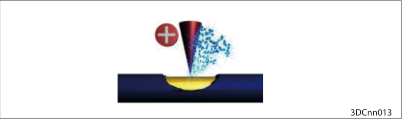
Contact of the cable with 24 volts
Short-circuits can occur in different places, for instance:
in plug connections due to warped contacts
at vibrating parts
in places where there is a lot of cable movement, e.g. in the joint of an articulation bus
where the cable passes close to sharp-edged parts
by foreign bodies inside plug connections or cables, e.g. dirt, moisture...
inside the transmission controller
Turn the ignition off.
Pull connector that carries the faulted signal out of the transmission controller and check contacts.
Use a multimeter set to resistance mode to check whether the short-circuit in the cable is still present.
Refer to circuit diagram to find out whether the short-circuit may have been caused by a connected electrical component. The fault possibilities are thus narrowed down.
If the electrical component is intact, disconnect all electrical components from the cable. Measure resistance between the signal line and
all lines conducting 24 volts
positive pole of battery
supply voltage of the transmission controller
measure all other lines at unplugged connector
Note the number of contacts at which a resistance value was measured that does not comply with the correct value.
Disconnect one after the other all connectors on which the faulted signal is present, check contacts.
Measure into each opened connection with the multimeter before disconnecting the next plug connection and track the short-circuit to the connecting point of the electrical component (e.g. kickdown switch).
If the measured value is correct, the short-circuit is located in the previous line section.
Recheck all contacts of the faulted line segment and look for defective spots.
If the fault cannot be localized, there may be a loose contact. The fault may be reproduced by shaking at the cables.
If abrasions, cable breaks, defective contacts or other defects have been detected, replace the affected cable or the electrical component.
Eliminate the defect causing the problem.
If you are certain that the short-circuit is not located outside the transmission controller, replace the controller with another one and check whether the fault has been eliminated.
If the fault has been eliminated due to the reproducibility of the fault, reinstall the original transmission controller.
If the fault recurs, the transmission controller is probably defective.
Order a controller with the same item number and install it in the vehicle.
If a signal is short-circuited to another signal, the cause is in most cases an abrasion or several mutually touching pins in a plug connection.
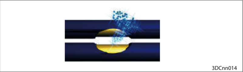
Contact of the cable with another cable
Short-circuits can occur in different places, for instance:
in plug connections due to warped contacts
at vibrating parts
in places where there is a lot of cable movement, e.g. in the joint of an articulation bus
where the cable passes close to sharp-edged parts
by foreign bodies inside plug connections or cables, e.g. dirt, moisture...
inside the transmission controller
Turn the ignition off.
Pull connector that carries the faulted signal out of the transmission controller and check contacts.
Use a multimeter set to resistance mode to check whether the short-circuit in the cable is still present. Accordingly, check resistance between the affected signal line and all other lines.
Refer to wiring diagram to find out whether the short-circuit may have been caused by a connected electrical component. The fault possibilities are thus narrowed down.
If the electrical component is intact, disconnect all electrical components from the cable. Accordingly, recheck resistance between the affected signal line and all other lines.
Check number of contacts that are short-circuited to each other. Disconnect one after the other all connectors on which the faulted signals are present, check contacts.
Measure with the multimeter into each opened connection before disconnecting the next plug connection.
If the measured value is correct, the short-circuit is located in the previous line section.
Recheck all contacts of the faulted line segment and look for defective spots.
If the fault cannot be localized, there may be a loose contact. The fault may be reproduced by shaking at the cables.
If abrasions, cable breaks, defective contacts or other defects have been detected, replace the affected cable or the electrical component.
Eliminate the defect causing the problem.
If you are certain that the short-circuit is not located outside the transmission controller, replace the controller with another one and check whether the fault has been eliminated.
If the fault has been eliminated due to the reproducibility of the fault, reinstall the original transmission controller.
If the fault recurs, the transmission controller is probably defective.
Order a controller with the same item number and install it in the vehicle.
A defective electrical component may be displayed as cable break (loose contact, jammed switching contact or too high line resistance).
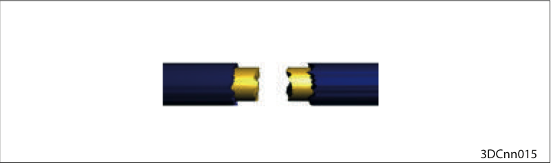
Cable break
Cable breaks can occur in different places, for instance:
at crimpings and plug-in contacts
at vibrating parts
in places where there is a lot of cable movement, e.g. in the joint of an articulation bus
where the cable passes close to sharp-edged parts
inside the transmission controller
Turn the ignition off.
Pull connector on which the interrupted signal applies out of the transmission controller and check contacts.
Refer to wiring diagram to find out whether the interruption may be caused by a connected electrical component. The fault possibilities are thus narrowed down.
If the electrical component is intact, insert a cable jumper at this end of the cable connection between the signal line and the return line required for the signal.
Use a multimeter set to resistance mode to measure between the signal line and the corresponding return line whether a cable break exists.
Disconnect one after the other all connectors on which the affected signal is present, check contacts.
Measure into each opened connection with the multimeter before disconnecting the next plug connection and track the cable break to the connecting point of the electrical component.
If the measured value is correct, the cable break is located in the previous line section.
Recheck all contacts of the faulted line segment and find defective spots.
If the fault cannot be localized, there may be a loose contact. The fault may be reproduced by shaking at the cables.
If abrasions, cable breaks, defective contacts or other defects have been detected, replace the affected cable or the electrical component.
Eliminate the defect causing the problem.
If you are certain that the interruption is not located outside the transmission controller, replace the controller and check whether the fault has been eliminated.
If the fault has been eliminated due to the reproducibility of the fault, reinstall the original transmission controller.
If the fault recurs, the transmission controller is probably defective.
Order a controller with the same item number and install it in the vehicle.
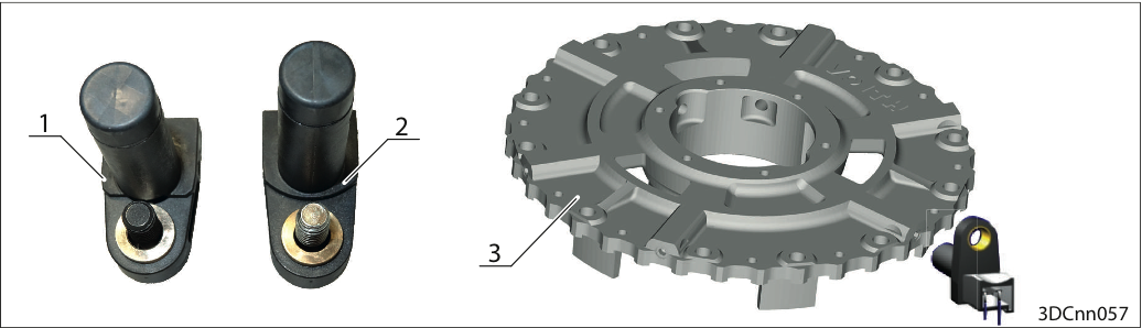
Check speed sensor N1 and disc carrier of the clutch
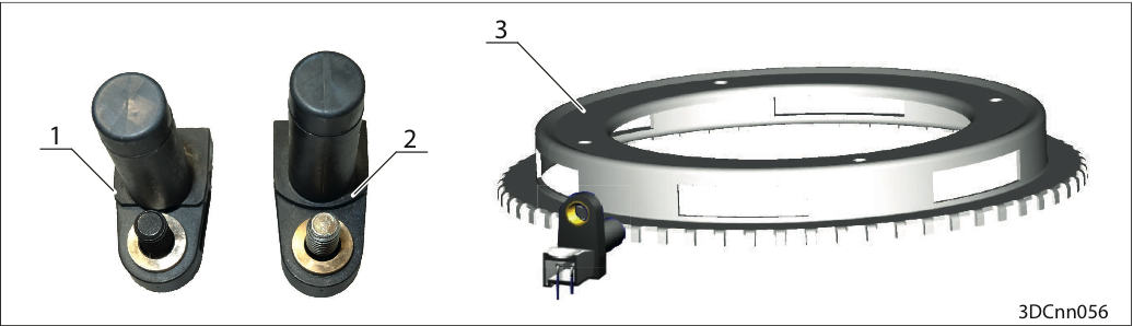
1. Sensor DIWA.5
2. Sensor DIWA.6 with rotation direction identification
3. Disc carrier of the clutch
Dismantle sensor N1.
Visually inspect sensor N1 (frequency transducer) and disc support of the clutch e.g. for mechanical damage (recognizable by the metal abrasion on the sensor → 1) and, if possible, for completeness of the teeth.
Clearance of sensor N1 – visually inspect the disc carrier of the clutch e.g. for signs of grinding on the sensor by the measurement gear.
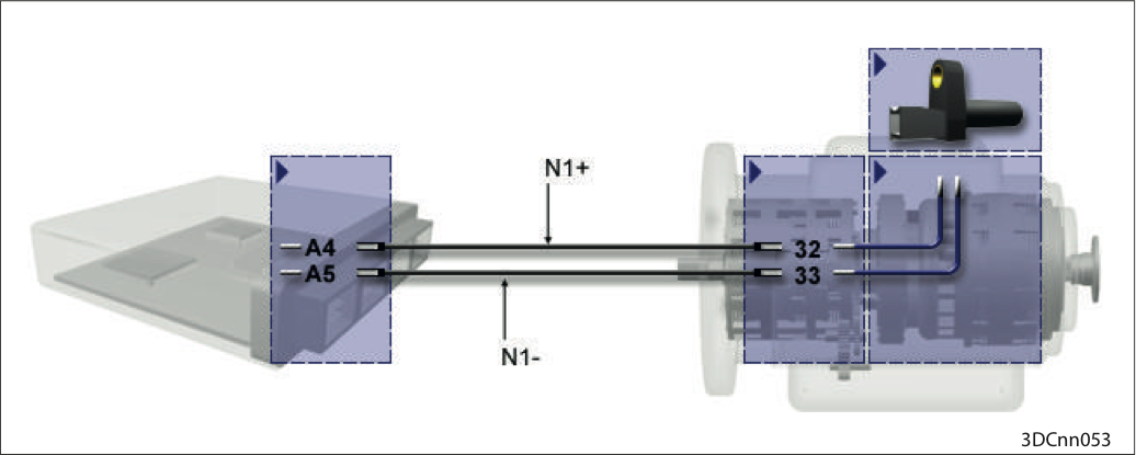
Connect sensor N1 with the transmission controller.
For a function check, connect sensor N1 with the transmission controller.
Create a signal with a metallic object (e.g. screwdriver).
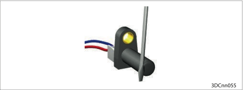
Check the frequency transducer
The metal object must be moved to and fro relative to the sensor in the plane in which the teeth of the measurement gear normally pass the sensor.
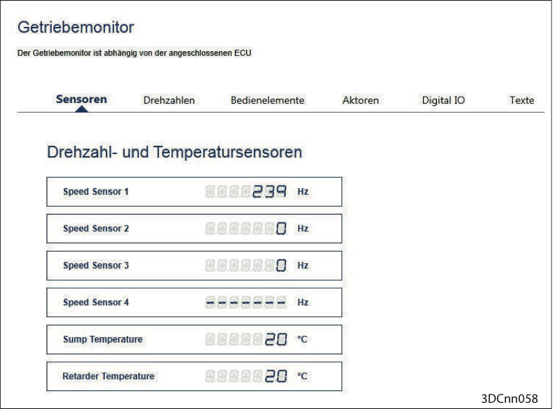
ALADIN test window "Transmission monitor"
Select the "Transmission monitor" button in ALADIN in the Service menu. A frequency signal must be displayed in the "Transmission monitor" test window of ALADIN.
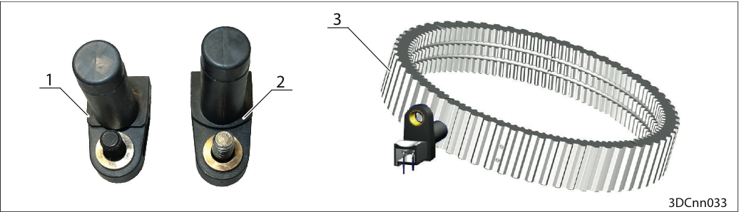
Check speed sensor N2 and counter wheel
1. Sensor DIWA.5
2. Sensor DIWA.6 with rotation direction identification
3. Counter wheel
Dismantle sensor N2.
Visually inspect sensor N2 (frequency transducer) and outer rim of reverse gear e.g. for mechanical damage (recognizable by the metal abrasion on the sensor → 1) and if possible for completeness of the teeth.
Clearance of sensor N2 – Visually inspect the outer rim e.g. for signs of grinding on the sensor by the measurement gear.
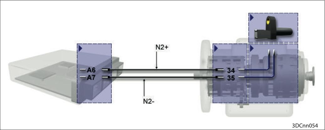
Connect sensor N2 with the transmission controller.
For a function check, connect sensor N2 with the transmission controller.
Create a signal with a metallic object (e.g. screwdriver).
Check the frequency transducer
The metal object must be moved to and fro relative to the sensor in the plane in which the teeth of the measurement gear normally pass the sensor.
ALADIN test window "Transmission monitor"
Select the "Transmission monitor" button in ALADIN in the Service menu. A frequency signal must be displayed in the "Transmission monitor" (→ 1) test window of ALADIN.
Check speed sensor N3 and outer rim of reverse gear
1. Sensor DIWA.5
2. Sensor DIWA.6 with rotation direction identification
3. Outer rim of reverse gear
Dismantle sensor N3.
Visually inspect sensor N3 (frequency transducer) and counter wheel e.g. for mechanical damage (recognizable by the metal abrasion on the sensor → 1) and if possible for completeness of the teeth.
Clearance N3 – Visually check counter wheel e.g. for signs of grinding on the sensor by the measurement gear
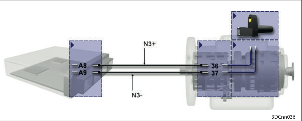
Connect sensor N3 with the transmission controller.
For a function check, connect sensor N3 with the transmission controller.
Create a signal with a metallic object (e.g. screwdriver).
Check the frequency transducer
The metal object must be moved to and fro relative to the sensor in the plane in which the teeth of the measurement gear normally pass the sensor.
ALADIN test window "Transmission monitor"
Select the "Transmission monitor" button in ALADIN in the Service menu. A frequency signal must be displayed in the "Transmission monitor" (→ 1) test window of ALADIN.
If the defective component cannot be clearly identified, you should try to reproduce the fault:
Reinstall the component in the vehicle.
Test function.
After the fault has been eliminated, the following steps have to be carried out:
Conduct a test drive with function check.
Read out fault memory.
Check transmission for leaks.
Perform a final visual inspection.
These steps are necessary to ensure the entire vehicle functions correctly.
Vehicle configuration! Depending on the vehicle configuration, different components are installed or different transmission functions are implemented. |  |
Accordingly, please read the vehicle's circuit diagram.
Connect the computer running the ALADIN diagnostic software to the transmission controller.
Read out the controller's identification data:
current software version,
current dataset.
Clear the fault memory!
Press one of the forward keys "D", "1", "2" or "3".
Start the engine.
The engine must not start.
Press the reverse gear key "R".
Start the engine.
The engine must not start.
Press the neutral key "N".
Step on the brake pedal.
Start the engine.
Engine starts up.
Press one of the gear keys.
The vehicle starts to drive.
Check the transmission functions, e.g.:
all up and downshifts.
Function of the converter brake (using the vehicle or transmission diagnostics).
Reverse.
ANS function.
Shift quality of the transmission with partial and full loads.
The safety function implemented in the vehicle according to the planning, e.g.:
gear acceptance with the vehicle stationary only when the brake pedal is depressed,
gear acceptance only up to the engine limit speed.
Read out the event memory.
Delete the event memory after eliminating the errors.
Check to make the transmission is not leaking.
Check to make sure the coolant water connections are not leaking.
Check the oil level.
Read out fault memory!