
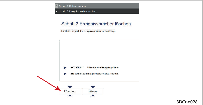
Clear event memory
Clear event memory.
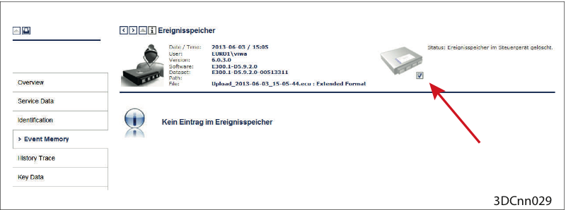
Event memory cleared
Event memory cleared (Check under ("Reporting > Event Memory > Check mark set")
Possibly test drive
Should the fault reoccur:
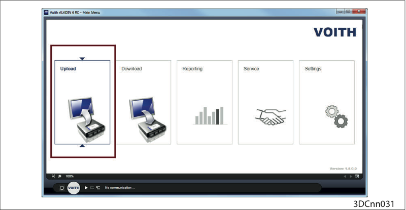
Upload
Perform an upload with the ALADIN diagnosis software.
Then please contact the VOITH customer service.
Check connectors, plug-in contacts, connector connections and cabling.
Check the connectors and their contacts for firm seating, interruption, short circuit, cable breakage and corrosion. The following chapters may be helpful:
Troubleshooting a short-circuit to ground→ Troubleshooting a short-circuit to ground
Troubleshooting for short-circuit to 24 volts→ Troubleshooting for short-circuit to 24 volts
Troubleshooting a short-circuit of two signals → Troubleshooting a short-circuit of two signals.
Troubleshooting for cable breakage → Troubleshooting for cable break
Possibly check pin assignment according to circuit diagram and measure contact resistances.
There may be several reasons why a short-circuit to ground is detected for a signal:
The signal line has contact to the chassis or to other elements linked to the battery ground
The signal line has contact to a ground cable (e.g. in the cable harness)
An electrical component is internally defective (e.g. switching contact is jammed)

Contact of cable to ground
Short-circuits can occur in different places, for instance:
in plug connections due to warped contacts
at vibrating parts
in places where there is a lot of cable movement, e.g. in the joint of an articulation bus
where the cable passes close to sharp-edged parts
by foreign bodies inside plug connections or cables, e.g. dirt, moisture...
inside the transmission controller
Turn the ignition off.
Pull connector that carries the faulted signal out of the transmission controller and check contacts.
Use a multimeter set to resistance mode to check whether the short-circuit in the cable is still present.
Refer to circuit diagram to find out whether the short-circuit may have been caused by a connected electrical component. The fault possibilities are thus narrowed down.
If the electrical component is intact, disconnect all electrical components from the cable. Measure resistance between the signal line and
all ground lines
battery ground and ground contact at transmission controller
measure all other lines at unplugged connector.
Note the number of contacts at which a resistance value was measured that does not comply with the correct value.
Disconnect one after the other all connectors on which the faulted signal is present, check contacts.
Measure into each opened connection with the multimeter before disconnecting the next plug connection and track the short-circuit to the connecting point of the electrical component (e.g. kickdown switch).
If the measured value is correct, the short-circuit is located in the previous line section.
Recheck all contacts of the faulted line segment and look for defective spots.
If the fault cannot be localized, there may be a loose contact. The fault may be reproduced by shaking at the cables.
If abrasions, cable breaks, defective contacts or other defects have been detected, replace the affected cable or the electrical component.
Eliminate the defect causing the problem.
If you are certain that the short-circuit is not located outside the transmission controller, replace the controller with another one and check whether the fault has been eliminated.
If the fault has been eliminated due to the reproducibility of the fault, reinstall the original transmission controller.
If the fault recurs, the transmission controller is probably defective.
Order a controller with the same item number and install it in the vehicle.
There may be a number of reasons why a short-circuit to 24 V is detected for a signal:
The signal line has contact to a line conducting 24 V (e.g. in the cable harness).
An electrical component is internally defective (e.g. switching contact is jammed)

Contact of the cable with 24 volts
Short-circuits can occur in different places, for instance:
in plug connections due to warped contacts
at vibrating parts
in places where there is a lot of cable movement, e.g. in the joint of an articulation bus
where the cable passes close to sharp-edged parts
by foreign bodies inside plug connections or cables, e.g. dirt, moisture...
inside the transmission controller
Turn the ignition off.
Pull connector that carries the faulted signal out of the transmission controller and check contacts.
Use a multimeter set to resistance mode to check whether the short-circuit in the cable is still present.
Refer to circuit diagram to find out whether the short-circuit may have been caused by a connected electrical component. The fault possibilities are thus narrowed down.
If the electrical component is intact, disconnect all electrical components from the cable. Measure resistance between the signal line and
all lines conducting 24 volts
positive pole of battery
supply voltage of the transmission controller
measure all other lines at unplugged connector
Note the number of contacts at which a resistance value was measured that does not comply with the correct value.
Disconnect one after the other all connectors on which the faulted signal is present, check contacts.
Measure into each opened connection with the multimeter before disconnecting the next plug connection and track the short-circuit to the connecting point of the electrical component (e.g. kickdown switch).
If the measured value is correct, the short-circuit is located in the previous line section.
Recheck all contacts of the faulted line segment and look for defective spots.
If the fault cannot be localized, there may be a loose contact. The fault may be reproduced by shaking at the cables.
If abrasions, cable breaks, defective contacts or other defects have been detected, replace the affected cable or the electrical component.
Eliminate the defect causing the problem.
If you are certain that the short-circuit is not located outside the transmission controller, replace the controller with another one and check whether the fault has been eliminated.
If the fault has been eliminated due to the reproducibility of the fault, reinstall the original transmission controller.
If the fault recurs, the transmission controller is probably defective.
Order a controller with the same item number and install it in the vehicle.
If a signal is short-circuited to another signal, the cause is in most cases an abrasion or several mutually touching pins in a plug connection.

Contact of the cable with another cable
Short-circuits can occur in different places, for instance:
in plug connections due to warped contacts
at vibrating parts
in places where there is a lot of cable movement, e.g. in the joint of an articulation bus
where the cable passes close to sharp-edged parts
by foreign bodies inside plug connections or cables, e.g. dirt, moisture...
inside the transmission controller
Turn the ignition off.
Pull connector that carries the faulted signal out of the transmission controller and check contacts.
Use a multimeter set to resistance mode to check whether the short-circuit in the cable is still present. Accordingly, check resistance between the affected signal line and all other lines.
Refer to wiring diagram to find out whether the short-circuit may have been caused by a connected electrical component. The fault possibilities are thus narrowed down.
If the electrical component is intact, disconnect all electrical components from the cable. Accordingly, recheck resistance between the affected signal line and all other lines.
Check number of contacts that are short-circuited to each other. Disconnect one after the other all connectors on which the faulted signals are present, check contacts.
Measure with the multimeter into each opened connection before disconnecting the next plug connection.
If the measured value is correct, the short-circuit is located in the previous line section.
Recheck all contacts of the faulted line segment and look for defective spots.
If the fault cannot be localized, there may be a loose contact. The fault may be reproduced by shaking at the cables.
If abrasions, cable breaks, defective contacts or other defects have been detected, replace the affected cable or the electrical component.
Eliminate the defect causing the problem.
If you are certain that the short-circuit is not located outside the transmission controller, replace the controller with another one and check whether the fault has been eliminated.
If the fault has been eliminated due to the reproducibility of the fault, reinstall the original transmission controller.
If the fault recurs, the transmission controller is probably defective.
Order a controller with the same item number and install it in the vehicle.
A defective electrical component may be displayed as cable break (loose contact, jammed switching contact or too high line resistance).

Cable break
Cable breaks can occur in different places, for instance:
at crimpings and plug-in contacts
at vibrating parts
in places where there is a lot of cable movement, e.g. in the joint of an articulation bus
where the cable passes close to sharp-edged parts
inside the transmission controller
Turn the ignition off.
Pull connector on which the interrupted signal applies out of the transmission controller and check contacts.
Refer to wiring diagram to find out whether the interruption may be caused by a connected electrical component. The fault possibilities are thus narrowed down.
If the electrical component is intact, insert a cable jumper at this end of the cable connection between the signal line and the return line required for the signal.
Use a multimeter set to resistance mode to measure between the signal line and the corresponding return line whether a cable break exists.
Disconnect one after the other all connectors on which the affected signal is present, check contacts.
Measure into each opened connection with the multimeter before disconnecting the next plug connection and track the cable break to the connecting point of the electrical component.
If the measured value is correct, the cable break is located in the previous line section.
Recheck all contacts of the faulted line segment and find defective spots.
If the fault cannot be localized, there may be a loose contact. The fault may be reproduced by shaking at the cables.
If abrasions, cable breaks, defective contacts or other defects have been detected, replace the affected cable or the electrical component.
Eliminate the defect causing the problem.
If you are certain that the interruption is not located outside the transmission controller, replace the controller and check whether the fault has been eliminated.
If the fault has been eliminated due to the reproducibility of the fault, reinstall the original transmission controller.
If the fault recurs, the transmission controller is probably defective.
Order a controller with the same item number and install it in the vehicle.
NOTICE
Damage to the transmission controller due to overvoltage!
Turn the ignition off prior to installation or removal.
Never expose the on-board electrical wiring to higher voltages than 45 V.
Do not touch any contacts to avoid ESD (electrostatic discharging) and soiling
Dismantle/replace the controller and send it to the Voith Customer Service for inspection.
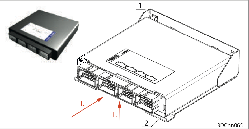
Dismantle the controller
Unplug connectors A, B, C, D (connector secured by "lug", lift "lug")
Press the device backwards (I.) against the springs (1).
List the device out of the rail (2) upwards (II.).
Pull out the device.
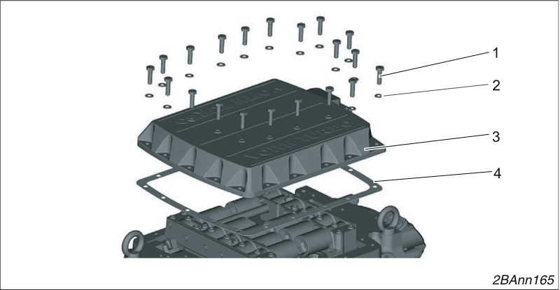
Removing the one-piece control block cover
Loosen 20 screws (1) and remove them with their washers (2).
Remove the cover (3).
Remove the seal (4).
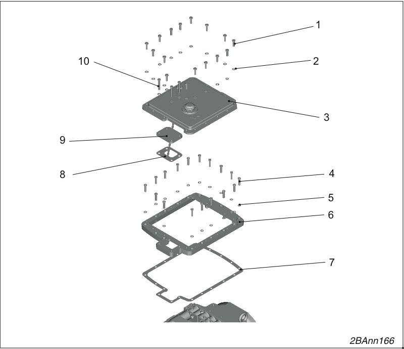
Remove the two-piece control block cover.
Loosen 13 screws (1) and remove them with their washers (2).
Remove the cover (3).
Remove the cover (9).
Remove the seal (8).
Loosen 13 screws (4) and remove them with their washers (5).
Remove the frame (6).
Remove the seal (7).
Installing the control block cover
Insert the new seal (4).
The seal must be free of grease when you install it.
Screw the control block cover (3) tight using 20 hexagon bolts M8 x 30 - 8.8 (1) and washers B 8.4 (2).
Tightening torque 23 Nm.
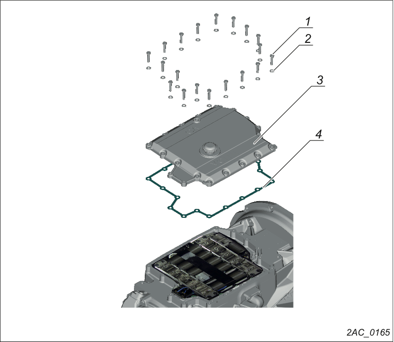
Removing the control block cover
Loosen 20 bolts (1) and remove them with 20 washers (2).
Remove the control block cover (3).
Remove the seal (4).
Installing the control block cover
Insert the new seal (4).
The seal must be free of grease when you install it.
Screw the control block cover (3) tight using 20 hexagon bolts M8 x 30 - 8.8 (1) and washers B 8.4 (2).
Tightening torque 23 Nm.
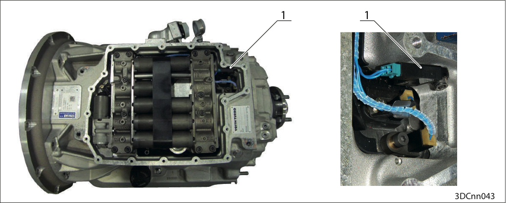
Position IM DIWA.6 (1)
Position IM DIWA.5 (2)
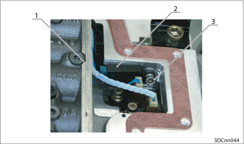
Remove the control block cover
Pull the cable (1).
Loosen the hexagon socket head bolt (3).
Remove the IM (2) from the transmission housing.
Reinstall the IM in reverse order.
Torque 14 Nm (for M6 screw)
Clear event memory
Clear event memory.
Event memory cleared
Event memory cleared (Check under ("Reporting > Event Memory > Check mark set")
Possibly test drive
Should the fault reoccur:
Upload
Perform an upload with the ALADIN diagnosis software.
Then please contact the VOITH customer service.