
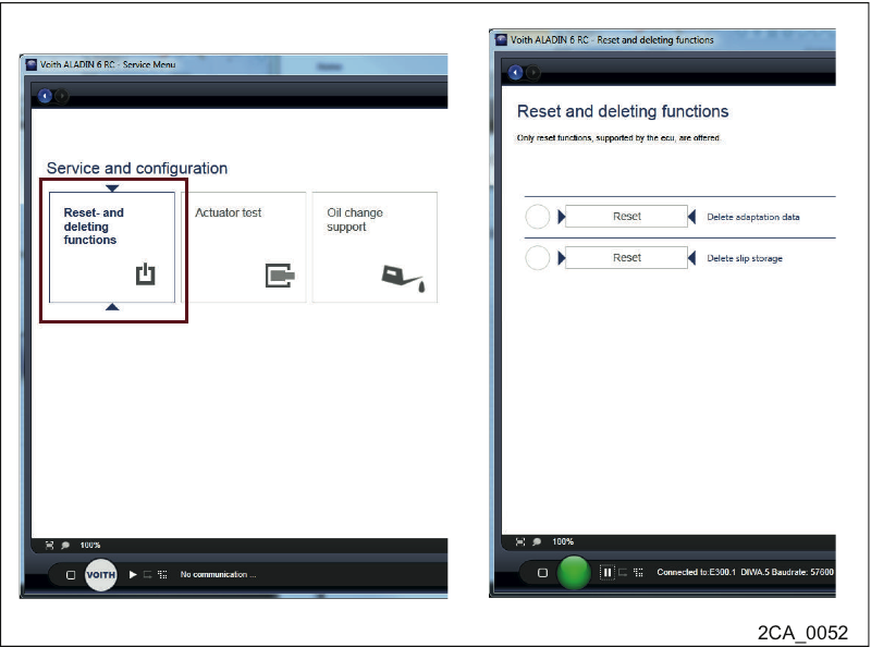
Reset the adaptation / fin slippage values
Select the button Service > Reset functions in ALADIN.
Reset the adaptation / fin slippage values.
Perform a test drive.
Read out the fault memory again (carry out an upload).
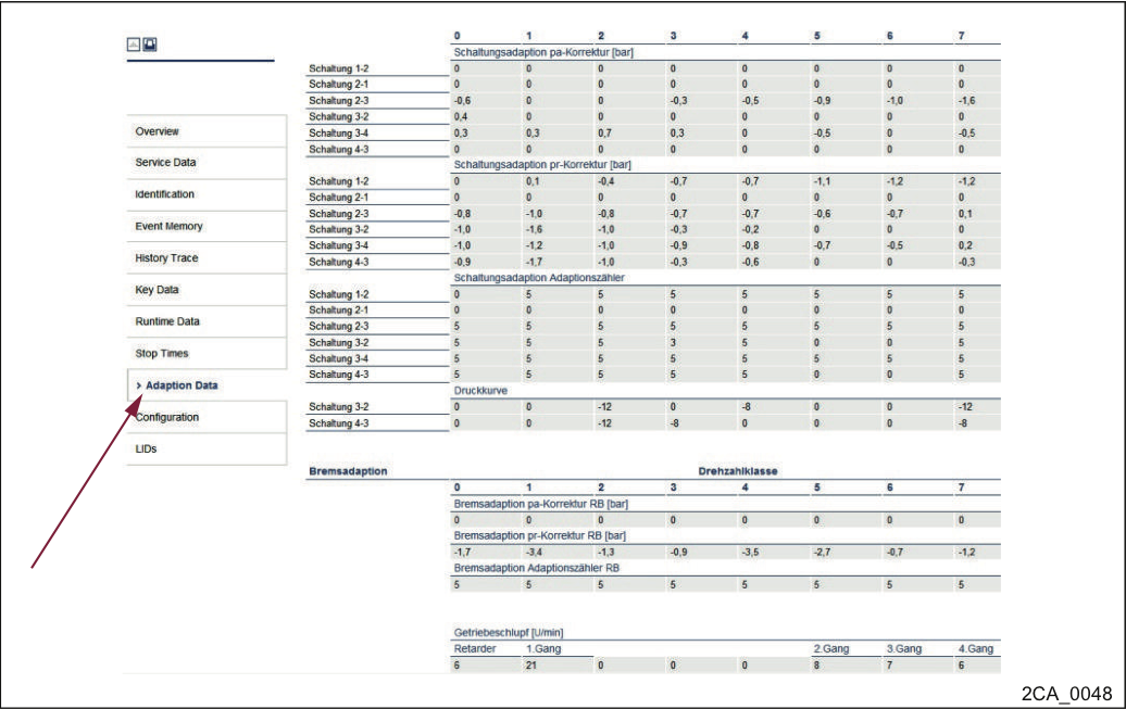
Reading out the adaptation / fin slippage values
Read out the adaptation value range.
Do not forget to grease the shaft (Gleitmo 805). Possibly observe service bulletin for protective cap and Gleitmo.
DANGER
Danger of accident due to unsecured vehicle!
The vehicle can start to move accidentally and cause severe accidents.
Apply the parking brake.
Secure the vehicle against rolling away.
Environmental hazard due to coolant! The used coolant must not enter the environment. Collect the coolant in an appropriate container. The coolant must be disposed of in accordance with the local regulations. |  |
Press the N key on the pushbutton selector.
Switch off the motor.
Turn off the ignition of the vehicle.
Unplug Voith cable 1 from the controller.
Drain the coolant.
Before cleaning the transmission with water or steam jet (high-pressure cleaner) or other cleaning agents, seal any openings into which no water, steam or cleaning agent may enter for reasons of safety and functioning.
Exterior oil hose lines must not be directly exposed to the jet of the high-pressure cleaner.
After cleaning, completely remove all covers/adhesives.
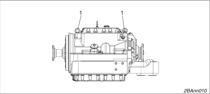
Suspension points
1. Ring bolts M12
Only use the suspension points (1) to attach the transmission to an appropriate lifting device that assures even weight distribution (observe the Safety chapter).
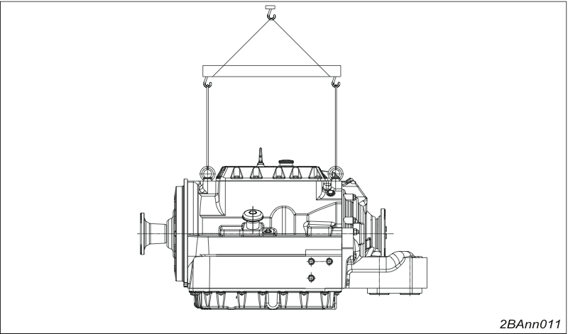
Suspension points
The ring bolts may only be loaded vertically upward
The maximum weight allowed to be attached to the eyebolts is the weight of the transmission with heat exchanger and angle drive.
It is not permitted to lift any additional loads at the eyebolts.
If the transmission is heavily soiled, clean before repair (observe the safety chapter).
After removing, clean all parts.
Replace all removed sealing elements.
Mount all flat seals without using grease.
Even if they are stored properly and not stressed beyond the allowed limits, hoses and hose lines are subject to a natural ageing process. Therefore, the time during which they may be used is limited.
DIN 20066: The usage duration of a hose line including storage duration may not exceed 6 years.
If a transmission is stored after repair without a test run, it must be protected against corrosion during storage.
NOTICE
The hydrodamp might be damaged if the transmission input shaft is moved in improperly!
Damage to the hydrodamp!
When inserting the shaft, make sure that the shaft is not tilted.
Apply gleitmo® 805 to the gear teeth of the transmission input shaft.
Move the transmission onto the engine.
The flywheel housing must be parallel to the transmission flange on the input side.
If the transmission input shaft and hydrodamp hub are aligned tooth-on-tooth, turn the transmission input shaft until the gear teeth are engaged properly.
Insert the drive input shaft into the hydrodamp.
Move the transmission up to the hydrodamp until the transmission flange on the input side rests against the flywheel housing.
Screw the input-side transmission flange to the flywheel housing.
Tightening torque 46 Nm.
NOTICE
Transmission damage due to improper installation of the universal joint shaft!
If the two parts of the universal joint shaft are installed incorrectly, irregular rotations can occur as a result causing critical torsional vibrations especially at high speeds.
When installing the two parts of the universal joint shaft, make sure that they are aligned correctly with each other and observe the markings.
Mount and screw on the universal joint shaft.
The installation instructions and safety notes of the manufacturer of the vehicle or the universal joint shaft must be observed.
The heat exchanger bears markings that indicate how to make the connections:
water out
oil in
oil out
water in
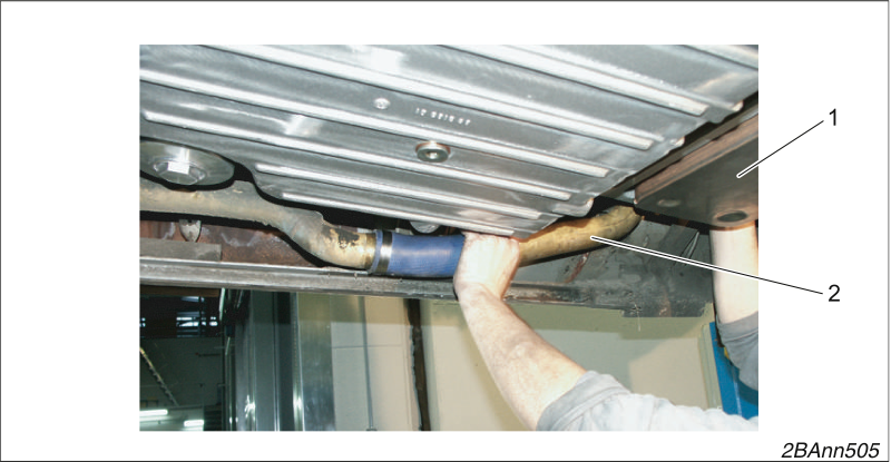
Heat exchanger connections
Mount the water pipes of the heat exchanger (2).
Fasten electrical connections such as:
Speedometer
Oscillator
Cable 1
NOTICE
The cable harness and cable 1 come with either gold-plated or tin-plated contacts (see Service Bulletin 173a)!
Contacts may only be connected if they are plated alike (gold - gold, tin-plated - tin-plated).
Only plug gold on gold contacts.
Only plug tin-plated on tin-plated contacts.
The contacts will be destroyed when linking contacts of different material.
All cable connections must be latched properly and fastened tightly.
Fill in cooling water up to the maximum level. Please observe the manufacturer's instructions.
Fill the transmission with oil.
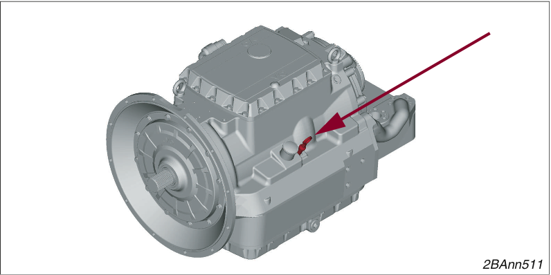
Oil dipstick on the side
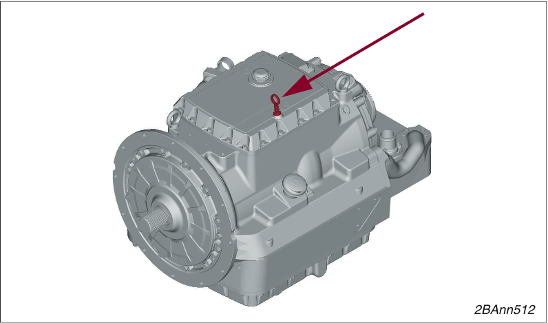
Oil dipstick on top
Place the vehicle in horizontal position.
Apply the parking brake.
Press the N key.
NOTICE
Transmission damage due to missing oil
If the engine is started and the transmission has not yet been filled with oil, e.g. after transmission repair, the transmission can receive considerable damage as a result.
After repair of the transmission, check the oil level when the engine is not running.
If there is insufficient oil in the transmission, refill some oil.
Measurement conditions In order to determine the correct value under operating conditions, the oil level must be checked with the engine running and at operating temperature (at least 60°C). The cooling water temperature indicator in the vehicle can be used to determine the transmission oil temperature because the transmission oil and cooling water temperatures are almost identical. | |
Start the engine.
Let the engine run in idle.
If the transmission oil temperature is below 60 C:
Let the engine warm up to operating temperature.
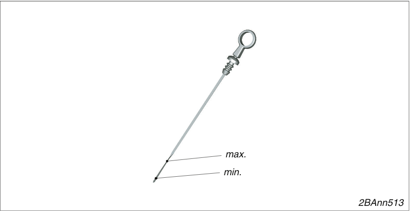
Oil dipstick
Pull out the oil dipstick.
Clean the oil dipstick.
The oil dipstick can be located to the side of or on top of the transmission.
Insert the oil dipstick briefly and remove.
Read the oil level.
The oil level must lie between the "min" and "max" markings of the oil dipstick.
The difference in amount between the two markings is approx. 2.5 l.
If there is no or insufficient oil in the transmission, replenish oil.
(Position of the oil filling opening → Position of the oil filling opening).
The transmission may only be filled with oil types that are specified in the current version of the Voith lubricant lists H55.6335.. and H55.6336..
After having filled in the oil, inspect the oil level and check the transmission for leaks.
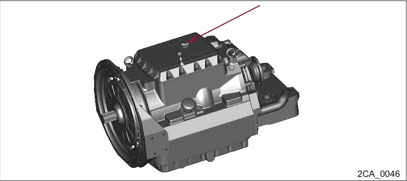
Oil filling opening on top
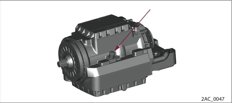
Oil filling opening on the side
WARNING
Risk of scalding due to hot oil!
Direct contact of the hot transmission oil with the skin can cause severe scalding injuries.
Take appropriate safety precautions when handling hot oil.
Shut off the engine.
Check the transmission oil temperature.
Risk of environmental pollution through oil! The used oil must not enter the environment. Collect the oil in an appropriate container. The oil must be disposed of in accordance with the local regulations. | |
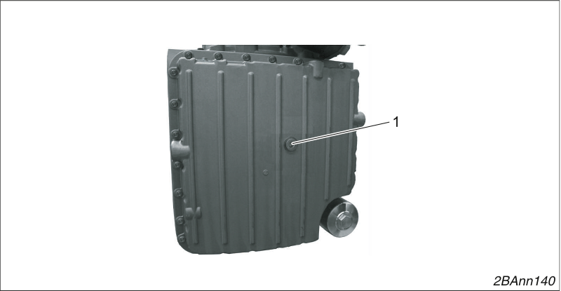
Oil pan drain plug
1. Oil pan drain plug
Loosen and remove the drain plug of the oil pan (1).
Use a hexagon socket wrench, size 12.
Drain the transmission oil.
Screw in the converter drain plug (2) with a new copper sealing ring 14 x 20.
Tighten the drain plug.
Tightening torque 50 Nm.
Screw in the oil pan drain plug (1) with a new copper sealing ring 26 x 34.
Tighten the drain plug.
Tightening torque 100 Nm.
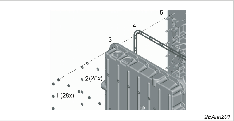
Oil pans with 28 stud bolts
Loosen and remove the 28 hexagon nuts (1).
Remove the 28 washers (2).
Carefully remove the oil pan (3) from the housing (5) by means of the stud bolts.
Remove the seal (4).
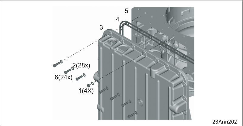
Oil pan with 4 stud bolts
Loosen and remove the 24 hexagon bolts (6).
Loosen and remove the 4 hexagon nuts (1).
Remove the 28 washers (2).
Carefully remove the oil pan (3) from the housing (5) by means of the stud bolts.
Remove the seal (4).
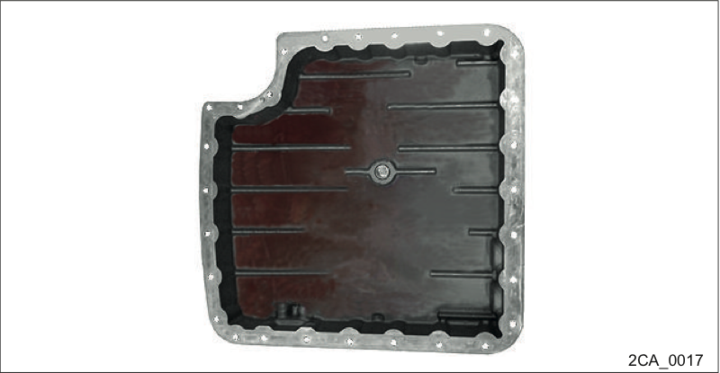
Checking the oil pan
Mechanical damage in the transmission.
Dismount oil pan.
If there is abraded matter, chips, metal parts or similar in the oil pan, there is mechanical damage to the transmission. In this case, notify the Voith customer service
If the oil pan is clean, there is probably no mechanical damage to the transmission.
The oil pan must be installed with a new seal. | |
Mounting the oil pan
Apply the new seal (4).
The seal must be mounted without grease.
Screw the oil pan (3) tight using 28 hexagon nuts (1) with 28 washers (2) placed underneath.
Tightening torque 23 Nm.
The oil pan must be installed with a new seal. | |
Mounting the oil pan
Apply the new seal (4).
The seal must be mounted without grease.
Screw on the oil pan (3) with 4 hexagon nuts (1), with 4 washers (2) placed underneath.
Screw the oil pan (3) tight using 24 hexagon bolts (6) with 24 washers (2) placed underneath.
Tightening torque 23 Nm.
Perform actuator test (→ Perform actuator testPerform actuator test).
Removing the control block cover
Remove the control blocks (→ Removing control blocks).
Take apart the control blocks (→ Taking apart the control blocks.).
Check valves (→ Checking valves).
Assemble the control blocks (→ Assembling the control blocks).
Mount control blocks (→ Mounting control blocks).
Mount the control block cover (→ Installing the DIWA.5 control block coverInstalling the DIWA.5 control block cover).
Perform an actuator test again to check (→ Perform actuator testPerform actuator test).
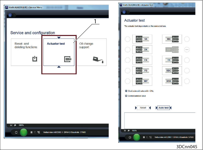
Perform actuator test
Call the button "Actuator test" (1) in ALADIN under the "Service" button.
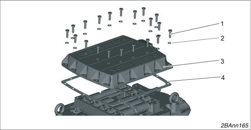
Removing the one-piece control block cover
Loosen 20 screws (1) and remove them with their washers (2).
Remove the cover (3).
Remove the seal (4).
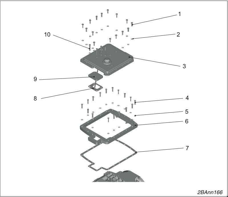
Remove the two-piece control block cover.
Loosen 13 screws (1) and remove them with their washers (2).
Remove the cover (3).
Remove the cover (9).
Remove the seal (8).
Loosen 13 screws (4) and remove them with their washers (5).
Remove the frame (6).
Remove the seal (7).
Installing the control block cover
Insert the new seal (4).
The seal must be free of grease when you install it.
Screw the control block cover (3) tight using 20 hexagon bolts M8 x 30 - 8.8 (1) and washers B 8.4 (2).
Tightening torque 23 Nm.
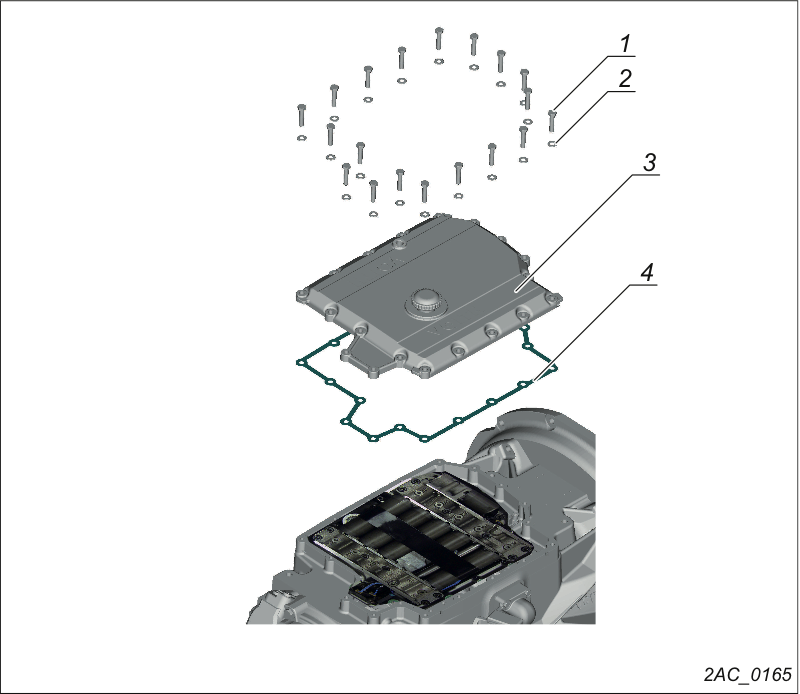
Removing the control block cover
Loosen 20 bolts (1) and remove them with 20 washers (2).
Remove the control block cover (3).
Remove the seal (4).
Installing the control block cover
Insert the new seal (4).
The seal must be free of grease when you install it.
Screw the control block cover (3) tight using 20 hexagon bolts M8 x 30 - 8.8 (1) and washers B 8.4 (2).
Tightening torque 23 Nm.
Order number H68.1535xx
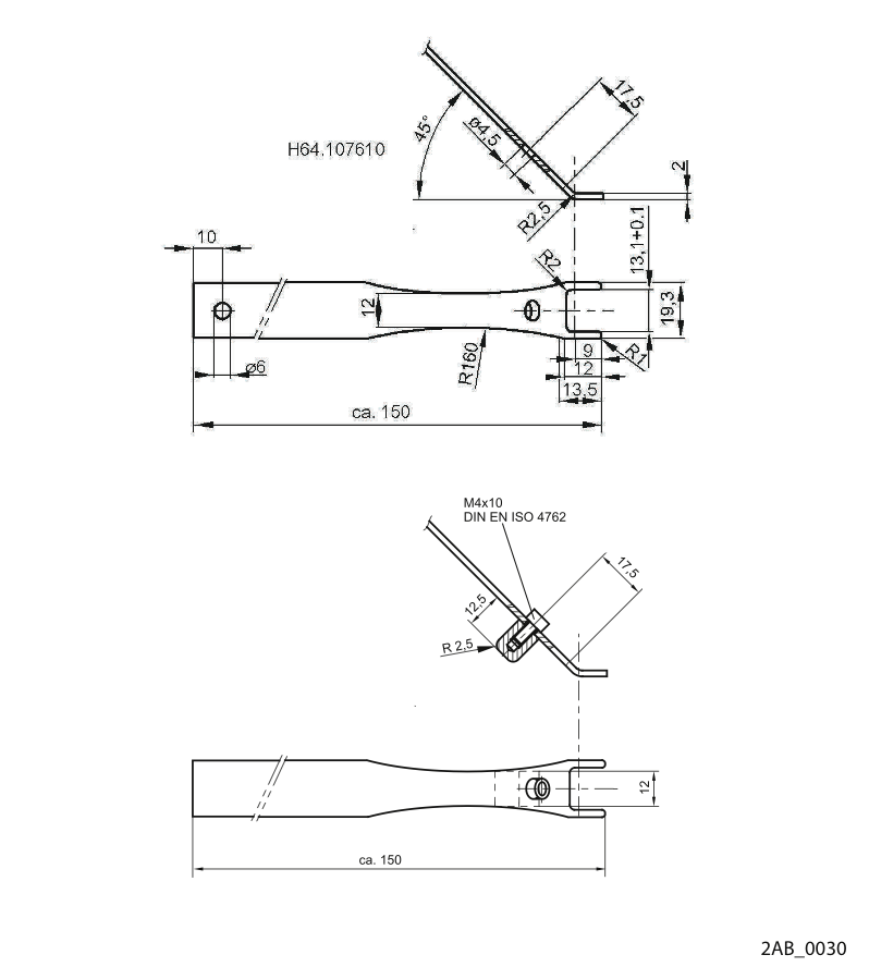
Tool for loosening the cable connectors from the solenoid coils
Order number 150.000145xx
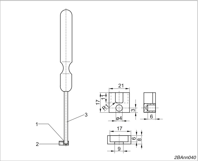
Tool for plugging the cable connectors into the solenoid coils
1. Hard-soldered
2. Insert for assembly tool
Order number 150.000144xx
3. Screwdriver DIN 5265-C-A 0,
8x4, tip removed
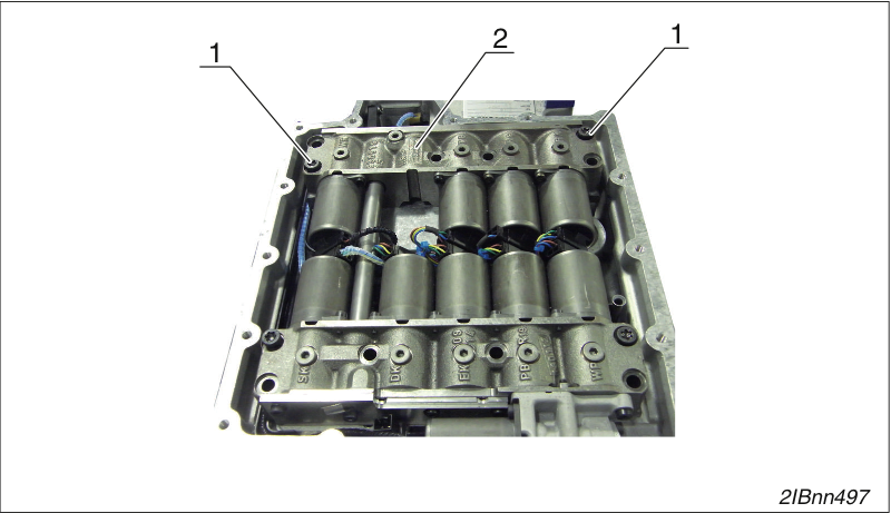
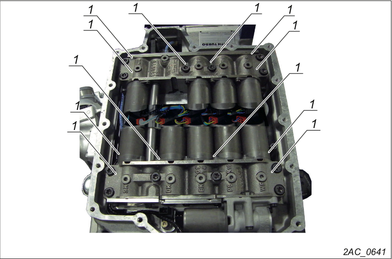
In the future, the modified cable guard of the DIWA.6 transmission will be used in DIWA.5 transmissions. If the cable guard in a DIWA.5 transmission has to be replaced, then only the new version of the cable guard is available as a spare part. If the cable guard has to be replaced, then the new version of the cable tray must also be used since only the new versions or the previous versions can be installed together. A mixed installation is not possible. | |
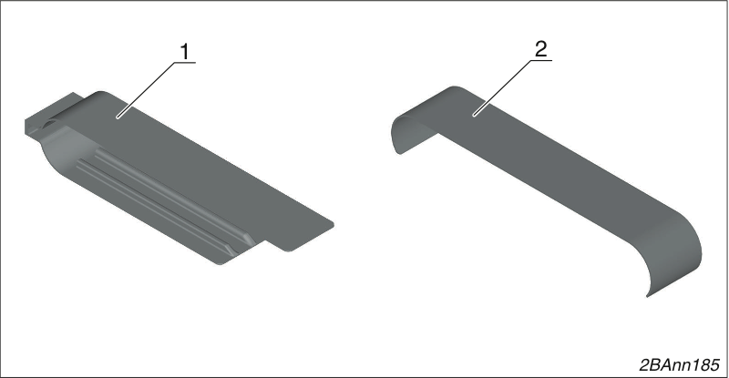
Cable guard
1. Previous version
2. New version
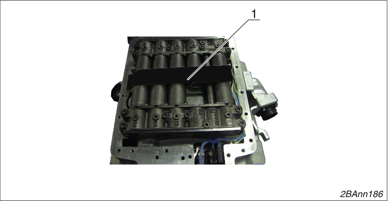
Remove the cable guard
Remove the cable guard (1)
NOTICE
The connection between the plug and cable can be damaged.
To loosen the cable connectors from the solenoid coils, use the special tool.
Never pull on the cables.
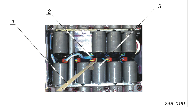
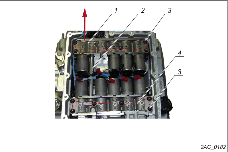
Removing control blocks
Pull off cable plug (1) from the solenoid coils.
Use the special tool (→ 1).
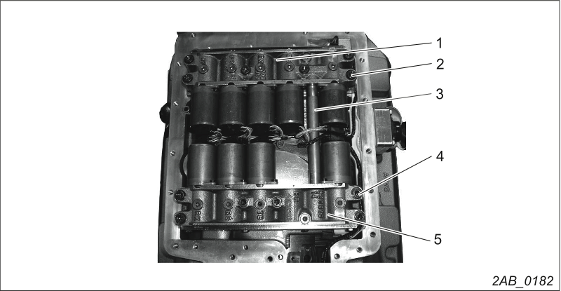
Removing control blocks
Loosen and remove the 12 socket head screws M8x50 (2).
Remove the spring washers 8 (12x) underneath these.
Remove control blocks (1 and 4).
Pull out connecting tube (3).
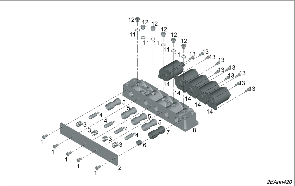
Take apart the input-side control block
Release 5 hexagon bolts (1) and remove cover (2).
Loosen all screw plugs M10 (12) and remove them with the sealing rings (11).
Otherwise, the pistons cannot be dismantled.
Dismount the following parts from the housing (8):
4 pistons (5)
4 control pins (4)
4 pressure springs (3)
Pistons (7)
Pressure spring (6)
Loosen 10 socket head screws M 5 x 20 – CV84 (13) and remove
5 solenoid coils (14).
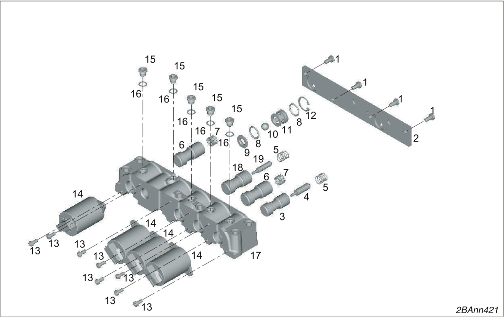
Dismounting the output-side control block
Release 4 hexagon bolts (1) and remove cover (2).
Loosen all screw plugs M10 (15) and remove them with the sealing rings (16).
Otherwise, the pistons cannot be dismantled.
Dismount the following parts from the housing (17):
Pistons (3, 18)
Control pin (4, 19)
2 pressure springs (5)
2 pistons (6)
2 pressure springs (7)
Dismount the insert (9), 2 O-rings (8), ball (10), valve body (11) and locking ring (12).
Loosen the 8 socket head screws M 5 x 20 (13) and dismount 4 solenoid coils (14).
Check the valves for smooth running.
If necessary, make the valves run smoothly (e.g. polish, hone...) or replace them.
NOTICE
Risk of mounting the pistons incorrectly!
If the pistons are mounted incorrectly, transmission malfunctions may occur during operation.
Make sure that spools are mounted in the correct position and run smoothly.
Assembling the input side (drive side) control block
Use 10 socket head screws M 5 x 12 - CV84 (13) to screw the 5 solenoid coils (14) tight.
Tightening torque 5 Nm.
The connections must be on top.
Mount the following parts in the housing (8) again:
4 pistons (5)
4 control pins (4)
4 pressure springs (3)
Pistons (7)
Pressure spring (6)
Screw the cover (2) tight using 5 hexagon bolts (1) M6 x 12 - 8.8.
Tightening torque 9 Nm.
Screw in 5 screw plugs WP M10 x 1 (12) with sealing rings (11).
Tightening torque 15 Nm.
Assembling the output-side control block
Use 8 socket head screws M 5 x 12 - CV84 (13) to screw the 4 solenoid coils (14) tight.
Tightening torque 5 Nm.
The connections must be on top.
Mount the following parts in the housing (18) again:
Pistons (3, 18)
Control pin (4, 19)
2 pressure springs (5)
2 pistons (6)
2 pressure springs (7)
Mount the insert (9), 2 O-rings (8), ball (10), valve body (11) and locking ring (12).
Screw the cover (2) tight using 4 hexagon bolts M6 x 12 - 8.8 (1).
Tightening torque 9 Nm.
Screw in 5 screw plugs WP M10 x 1 (15) with sealing rings (16).
Tightening torque 15 Nm.
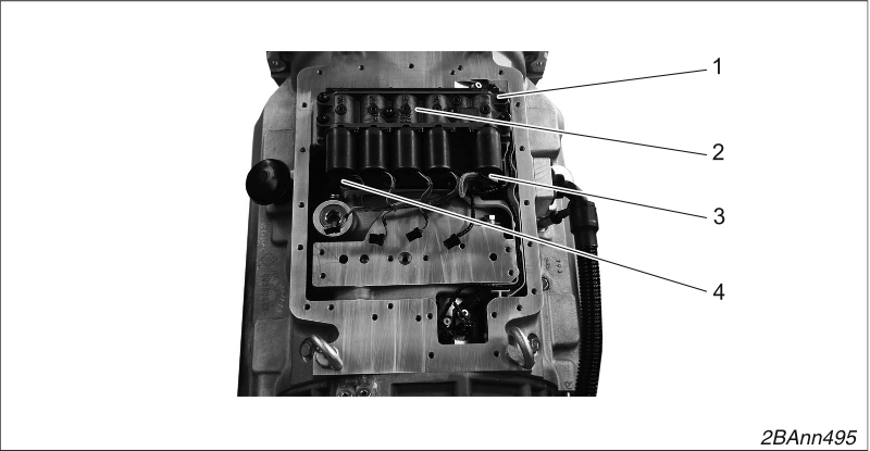
Mounting control blocks
Fix the control block (2) with 6 socket head screws M8 x 50 (1).
Plug 5 cable connectors (4) into the solenoid coils using the special tool (→ 1).
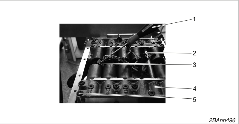
Mounting control blocks
Use a special tool (1) (→ 1) to insert the cable plugs (3) into the
solenoid coils.
Mount the connecting tube (2) with new O-rings 12 x 2.
Fix the control block (4) with 6 socket head screws M8 x 50 (5).
Tighten 12 socket head screws M8 x 50.
Tightening torque 20 Nm.
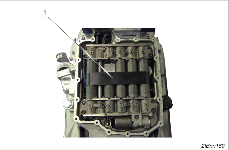
Remove the cable guard
Remove the cable guard (1)
NOTICE
The connection between the plug and cable can be damaged.
When unplugging the cable connectors → 1(1), the contacts between the cable connectors → 1/(1) and cables → 1/(2) can be damaged.
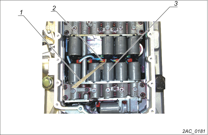
Unplugging the cable connectors
Unplug cable connector (2) from the solenoid coil (3).
Use special tool (1) (→ 1).
Unplug all cable connectors from all solenoid coils.
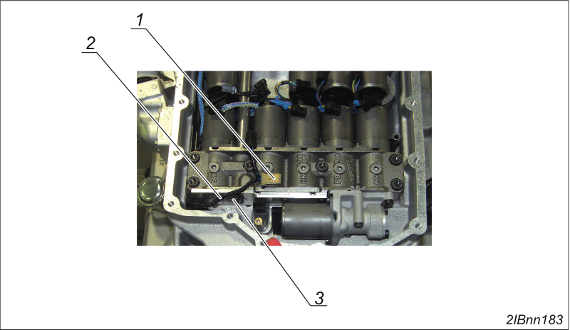
All cable connectors on the solenoid coils unplugged
Unplug connectors from the N1 sensor (1).
Carefully pull line (2) out of the holder (3).
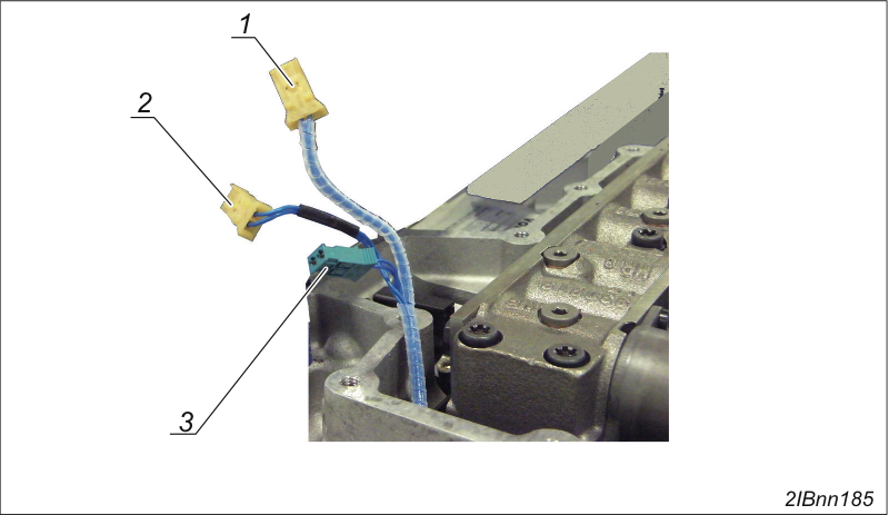
Unplugging the cable harness
Unplug connector (1) from the N2 sensor.
Unplug connector (2) from the N3 sensor.
Unplug connector (3) from the IM.
Removing control blocks
Loosen and remove the 12 socket head screws M8 x 50 (3).
Remove the spring washers 8 (12x) underneath these.
Pull the control block (1) carefully in the direction of the output until the connecting tube (2) comes out of the control block (1).
Carefully lift out the control block (1).
Pull out the connector tube.
Carefully lift out the control block (4).
Take apart the control blocks (→ Taking apart the control blocks.).
Check valves (→ Checking valves).
Assemble the control blocks (→ Assembling the control blocks).
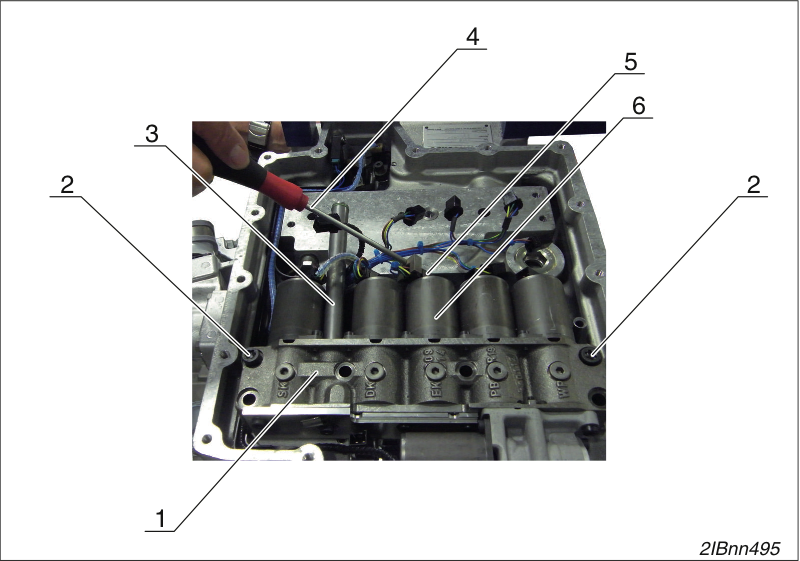
Mounting control blocks
Fix the control block (1) with 2 socket head screws M8 x 50 (2).
Install the connecting tube (3) with two new O-rings 12 x 2.
Plug the cable connector (4) into the solenoid coils (5) with the special tool (3) (→ 1).
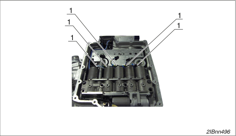
Mounting control blocks
Plug in all six cable connectors (1).
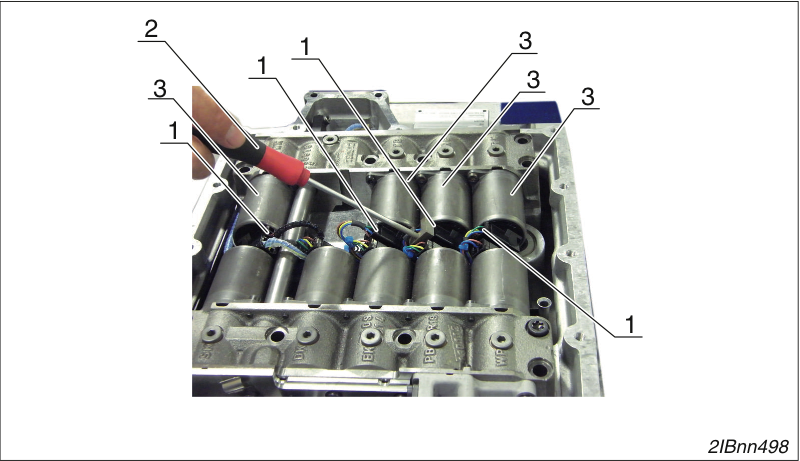
Mounting control blocks
Plug four cable connectors (1) into the solenoid coils (3) using the special tool (2) (→ 1).
Mounting control blocks
Fix the control block (2) with two socket head screws M8 x 50 (1).
Mounting control blocks
Tighten 12 socket head screws M8 x 50 (1).
Tightening torque 20 Nm.
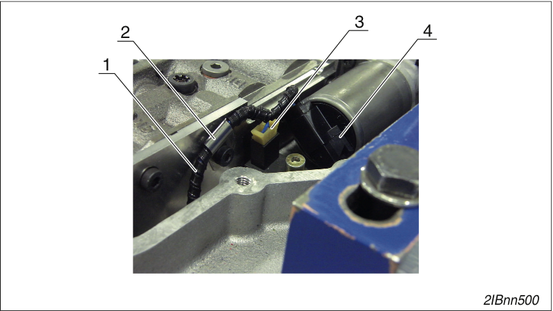
Inserting the cable harness
Insert the cable (1) into the holder (2).
Insert the plug for the speed sensor N1 (3).
Plug in the connector on the EO valve (4) with the auxiliary tool (→ 1).
Mounting control blocks
Mount the cable guard (1).
Removing the one-piece control block cover
Loosen 20 screws (1) and remove them with their washers (2).
Remove the cover (3).
Remove the seal (4).
Remove the two-piece control block cover.
Loosen 13 screws (1) and remove them with their washers (2).
Remove the cover (3).
Remove the cover (9).
Remove the seal (8).
Loosen 13 screws (4) and remove them with their washers (5).
Remove the frame (6).
Remove the seal (7).
Installing the control block cover
Insert the new seal (4).
The seal must be free of grease when you install it.
Screw the control block cover (3) tight using 20 hexagon bolts M8 x 30 - 8.8 (1) and washers B 8.4 (2).
Tightening torque 23 Nm.
Removing the control block cover
Loosen 20 bolts (1) and remove them with 20 washers (2).
Remove the control block cover (3).
Remove the seal (4).
Installing the control block cover
Insert the new seal (4).
The seal must be free of grease when you install it.
Screw the control block cover (3) tight using 20 hexagon bolts M8 x 30 - 8.8 (1) and washers B 8.4 (2).
Tightening torque 23 Nm.
Perform actuator test
Call the button "Actuator test" (1) in ALADIN under the "Service" button.
Check oil for colour and smell.
if in doubt, remove and check the oil pan
Order number H64.2157xx
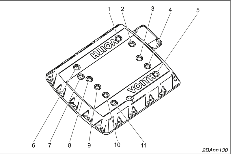
Measuring cover
1. WR
2. Converter pressure
3. TB
4. RG
5. RK
6. SK
7. Operating pressure
8. DK
9. EK
10. PB
11. WP

Accessories for measuring cover
Item | Designation | Qty. | Order number |
|---|---|---|---|
1 | Manometer with hoses and double sockets | 1 | H59.2093XX |
2 | Screw plug | 11 | H01.028689 |
3 | Measuring connection | 11 | H50.8802XX |
4 | Sealing ring | 11 | H50.0107XX |
Mount measuring cover only with engine dead.
Connect pressure gauge only with engine dead.
Depending on the design, it is possible that the connection point "Operating pressure" is no longer available. In this case, measure the "operating pressure" at connection point EK. | |
.
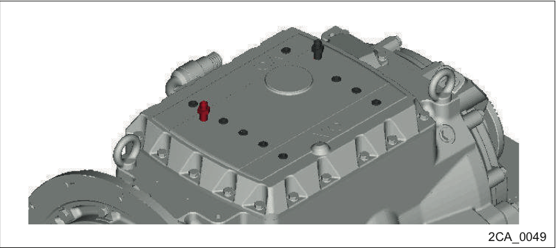
Measuring operating pressure
Measure operating pressure at the measuring point 7 (→ Measuring cover, tool).
Observe the setpoint for the operating pressure pA=8.5 bar, 9.5 bar or 10.5 bar (± 0.2 bar). Please refer to nameplate.
Measurement to be taken
immediately after shifting into second gear
at an engine speed of approx. 1500 rpm
at an oil temperature of 80-90°C
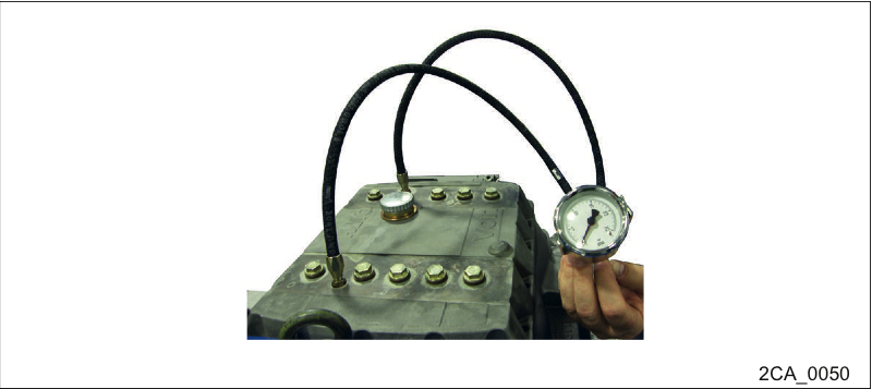
Measuring operating pressure
Connect the pressure gauge.
Connection thread M 12x1.5
Measuring range 0 to 25 bar
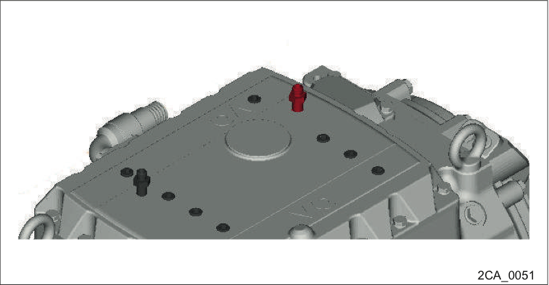
Measure the converter pressure
Measure the converter pressure at measuring point 2 (→ Measuring cover, tool).
Setpoint pW > 2 bar
Measurement to be taken at:
Oil temperature from 80-90 °C
Forward gear engaged
Engine at idle speed of approx. 500 +/- 50 rpm
Parking brake applied
Measure the converter pressure
Connecting the pressure gauge
Connection thread M 12x1.5
Measuring range 0 to 25 bar