
Terminal connection diagram 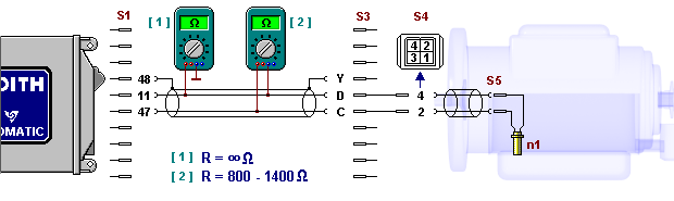
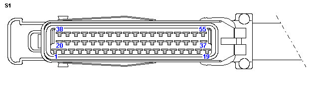
Test steps - Open plug connection S1. Measure resistance between socket contacts 11 and 47 of cable 1.
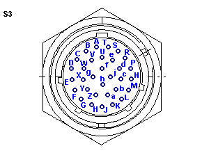
RTarget = 800-1400 Ω. If R = RTarget, continue with 5. - Open S3. Check resistance between pin contacts C and D of cable harness or N1 contacts of measuring cable. RTarget = 800-1400 Ω.
- Remove control cover. Open S4. Measure resistance between socket contacts 4 and 2 of terminal for inductive pickup N1. RTarget = 800-1400 Ω.
- Remove oil pan. Dismount gear pump with inductive pickup N1. Open S5. Measure resistance between pin contacts of inductive pickup N1. RTarget = 800-1400 Ω.
- Check resistance between contact 11 and vehicle ground at open plug connection S1.
RTarget = ∞ Ω. - Check resistance between contact 47 and vehicle ground. RTarget = ∞ Ω.
- Check resistance between contact C and ground at open plug connection S3.
RTarget = ∞ Ω. - Check resistance between contact D and ground. RTarget = ∞ Ω.
- Check resistance between contact 2 and ground at open plug connection S4.
RTarget = ∞ Ω. - Check resistance between contact 4 and ground. RTarget = ∞ Ω.
- Check resistance between each contact and ground at open plug connection S5.
RTarget = ∞ Ω.
|


