
Terminal connection diagram 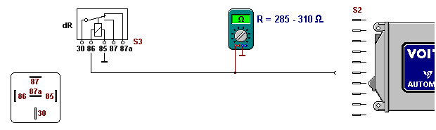
Test steps - Replace dR relay by a new one, or after removing the relay, measure the resistance directly between the winding contacts 85 and 86.
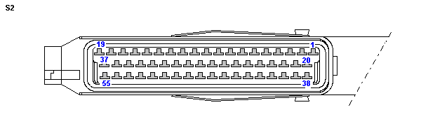
RTarget = 285-310 Ω. - Open S2 plug connection.
For the following steps, bring one test probe of the ohmmeter into contact with the vehicle ground. Measure resistance at corresponding contact of cable 2.
RTarget = 285-310 Ω.
If R = RTarget, continue with 4. - S3 socket connection: Measure resistance at supply cable to winding start of the dR relay (pin contact 86).
RTarget = 285-310 Ω. - S3: Measure resistance at supply cable to winding end of the dR relay (pin contact 85) and ground point M.
RTarget = 0 Ω.
Notice: variable signal The assignment to a connection of the transmission control unit is accomplished in the data record and is vehicle-specific. |


