Driving in 1st gear only. Higher gears at very high engine speed only (engine protection).
If a substitute function is available, the fault may cause hard shifts and hard retarder activation.
If the engine speed sensor is simultaneously defective, only limp-home mode is available.
Possible causes
Short-circuit in the sensor or in the sensor cabling.
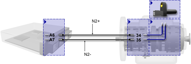
Connection of the speed sensor
Connector pin assignment of transmission control unit
Pin
Stecker A
Stecker B
Stecker C
Stecker D
1
SHIELD
EK
FLEXI-1
-BATT
2
TIM+
DK
---
IGN
3
TIM-
SK
FLEXI-3
FLEXI-11
4
N1+
RBK
FLEXI-4
K-LINE
5
N1-
TB
FLEXI-5
CAN1-H
6
N2+
---
FLEXI-6
CAN1-H
7
N2-
RBG
FLEXI-7
CAN-SHLD
8
N3+
PB
FLEXI-8
CAN1-L
9
N3-
WR
FLEXI-9
CAN1-L
10
---
WP
FLEXI-10
CAN2-H
11
---
---
FLEXO-2H
CAN2-H
12
EKM
FLEXI-12
FLEXO-4H
CAN2-L
13
DKM
S-GND
FLEXO-3H
CAN2-L
14
SKM
OIL-LVL
FLEXO-5L
CAN1-R
15
PBM
T-SUMP
---
---
16
TBM
---
---
FLEXO-1L
17
RBKM
T-CONV
---
CAN2-R
18
MVM-GND
MV-GND
---
+BATT
Pin assignment of transmission connector
Pin
Name
Pin
Name
Pin
Name
1
S-GND
14
RBK
27
EKM
2
MV-GND
15
RBG
28
PBM
3
MV-GND
16
TB
29
RBKM
4
---
17
WR
30
TBM
5
T-CONV
18
---
31
MVM-GND
6
T-SUMP
19
---
32
N1+
7
OIL-LVL
20
---
33
N1-
8
P-DIFF
21
TIM-
34
N2+
9
SK
22
TIM+
35
N2-
10
DK
23
---
36
N3+
11
EK
24
SHIELD
37
N3-
12
PB
25
SKM
13
WP
26
DKM
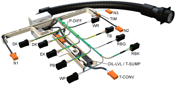
Internal cable harness
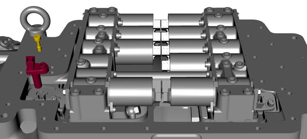
Installation point of the speed sensor
Place of action
Transmission output speed sensor
(sensor lines to each other)
Instruction
Check plug connections, cabling and sensor.
Setting conditions of the event
No description available.
Test conditions of the event
No description available.
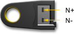
Speed sensor connector
N+ = supply connection N- = ground connection
Troubleshooting
Check the plug connections and cables. (Instruction: see "Related Topics")
Dismantle speed sensor out of transmission, but do not disconnect electrical plug connections. Create a signal with a metallic object (e.g. screwdriver). A signal should be displayed in the test window for monitoring frequencies. The object must be moved to and fro relative to the sensor in the plane in which normally the teeth of the measurement gear pass the sensor (see animation).
Replace speed sensor with a new one and check new sensor with a metallic object by means of the test window for monitoring frequencies.
Replace the control unit.
If none of the above measures brings any improvement, please contact the Voith Turbo headquarters.
Final function check
If the defective component cannot be clearly identified, you should try to reproduce the fault:
Reinstall the component in the vehicle.
Test the function.
After the fault has been eliminated, the following steps have to be carried out:
Conduct a test drive with function check.
Read out the fault memory.
Check the transmission for leaks.
Perform a final visual inspection.
These steps are necessary to ensure the entire vehicle functions.