
Description Short-circuit or low-resistance connection to ground of supply connection of measuring coil.
effects on the driving operation Hard shifts All gearshifts may be concerned, especially 3-2, ANS-1, N-1, N-2 and N-R shifts.
Possible causes Short-circuit in plug connection or cabling.
Connection of the solenoid valve 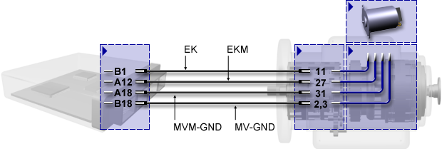
Connector pin assignment of transmission control unit | | | | Pin | Stecker A | Stecker B | Stecker C | Stecker D | | 1 | SHIELD | EK | FLEXI-1 | -BATT | | 2 | TIM+ | DK | --- | IGN | | 3 | TIM- | SK | FLEXI-3 | FLEXI-11 | | 4 | N1+ | RBK | FLEXI-4 | K-LINE | | 5 | N1- | TB | FLEXI-5 | CAN1-H | | 6 | N2+ | --- | FLEXI-6 | CAN1-H | | 7 | N2- | RBG | FLEXI-7 | CAN-SHLD | | 8 | N3+ | PB | FLEXI-8 | CAN1-L | | 9 | N3- | WR | FLEXI-9 | CAN1-L | | 10 | --- | WP | FLEXI-10 | CAN2-H | | 11 | --- | --- | FLEXO-2H | CAN2-H | | 12 | EKM | FLEXI-12 | FLEXO-4H | CAN2-L | | 13 | DKM | S-GND | FLEXO-3H | CAN2-L | | 14 | SKM | OIL-LVL | FLEXO-5L | CAN1-R | | 15 | PBM | T-SUMP | --- | --- | | 16 | TBM | --- | --- | FLEXO-1L | | 17 | RBKM | T-CONV | --- | CAN2-R | | 18 | MVM-GND | MV-GND | --- | +BATT |
Pin assignment of transmission connector | | | | Pin | Name | Pin | Name | Pin | Name | | 1 | S-GND | 14 | RBK | 27 | EKM | | 2 | MV-GND | 15 | RBG | 28 | PBM | | 3 | MV-GND | 16 | TB | 29 | RBKM | | 4 | --- | 17 | WR | 30 | TBM | | 5 | T-CONV | 18 | --- | 31 | MVM-GND | | 6 | T-SUMP | 19 | --- | 32 | N1+ | | 7 | OIL-LVL | 20 | --- | 33 | N1- | | 8 | P-DIFF | 21 | TIM- | 34 | N2+ | | 9 | SK | 22 | TIM+ | 35 | N2- | | 10 | DK | 23 | --- | 36 | N3+ | | 11 | EK | 24 | SHIELD | 37 | N3- | | 12 | PB | 25 | SKM | | | | 13 | WP | 26 | DKM | | |
Internal cable harness 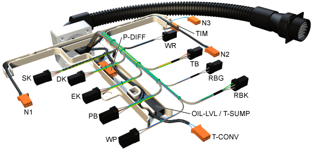
Installation point of the solenoid valve 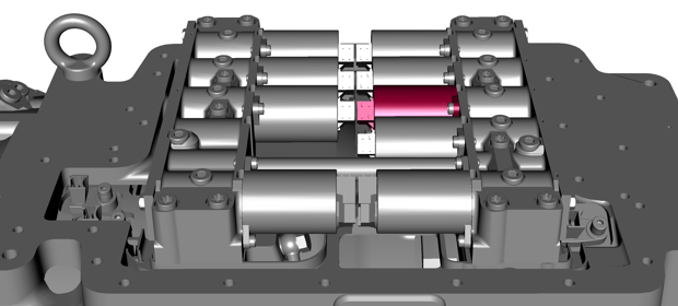
Place of action Cabling between the positive terminal of the measuring coil of the solenoid valve EK and the transmission control unit
Instruction Check plug connections and cabling.
Setting conditions of the event No description available.
Test conditions of the event No description available.
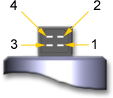
Connector controllable solenoid valve Pin assignment for solenoid valve
4 = operating coil: connection to supply
2 = operating coil: connection to ground
1 = measuring coil: connection to supply
3 = measuring coil: connection to ground |
| 
|
Troubleshooting - Check plug connections and cables.
- Pull connector at solenoid.
Check that solenoid is internally intact:
When measuring the coil resistances, please observe the dependence on the temperature.
Simultaneously to the resistance measurement, the temperature of the solenoid enclosure has to measured, too, or estimated with utmost accuracy. Read the nominal resistance indicated in the temperature curve below and compare it to the measured or estimated temperature.
Operating coil
Measure the resistance between pin 4 and pin 2.
The operating coil works correctly if the measured resistance deviates from the nominal resistance by not more than ± 1 Ω.
Measuring coil
Measure the resistance between pin 1 and pin 3.
The measuring coil works correctly if the measured resistance deviates from the nominal resistance by not more than ± 0.5 Ω.
No resistance – no connection – must be measurable between the pins and the solenoid enclosure; the resistance is infinitely large. - Replace the control unit.
- If none of the above measures brings any improvement, please contact the Voith Turbo headquarters.
Pin assignment for solenoid valve
4 = Operating coil: Supply connection
2 = Operating coil: Ground connection
1 = Measuring coil: Supply connection
3 = Measuring coil: Ground connection |
|
|
Characteristics:
A = Operating coil
B = Measuring coil 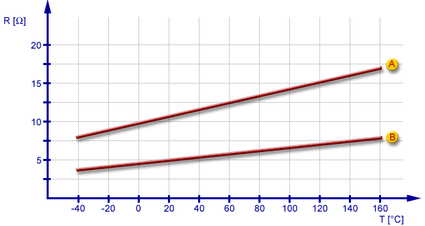
Final function check If the defective component cannot be clearly identified, you should try to reproduce the fault: - Reinstall the component in the vehicle.
- Test the function.
After the fault has been eliminated, the following steps have to be carried out: - Conduct a test drive with function check.
- Read out the fault memory.
- Check the transmission for leaks.
- Perform a final visual inspection.
These steps are necessary to ensure the entire vehicle functions.
See also: | 



























