| ||||||||||||||||||||||||||||||||||||||||||||||||||||||||||||||||||||||||||||||||||||||||||||||||||||||||||||||||||||||||||||||||||||||||||||||||||||||||||||||||||||||||||||||||||||||||||||||||||||||||||||||||||||||||||||||||||||||||||||||||||||||||||||||||||||||||||||||||||||||||||||||||||||||||||||||||||||||||||||||||||||||||||||||||||||||||||||||||||||||||||||||||||||||||||||||||||||||||||||||||||||||||||||||||||||||||||||||||||||||||||||||||||||||||||||||||||||||||||||||||||||||||||||||||||||||||||||||||||||||||||
Description Communication on the CAN bus is disturbed due to ´CAN warning´ conditions. A ´CAN warning´ is caused by a CAN controller receiving too many invalid data. A CAN controller in warning condition can still read data from the CAN bus but it can no longer send data. The warning condition is automatically cancelled once the CAN controller has received a certain percentage of valid data.
Effects on the driving operation Transmission shifts sporadically to neutral. Lighting of the gear range selector becomes dark.
Possible causes CAN bus incorrectly terminated (bus terminating resistor). There is a cable break, loose contact or too high contact resistance in the CAN cabling.
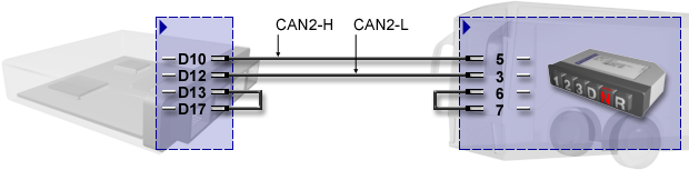
Connection of the CAN gear selector switch
The jumpers on the transmission control unit (D13 to D17) and on the CAN gear range selector (6 to 7) activate the integrated CAN terminating resistors since the transmission control unit and the CAN gear range selector are usually the only CAN bus nodes at CAN2. The CAN bus must always be wired with the terminating resistors on both sides.
Connector pin assignment of transmission control unit
Connector pin assignment of CAN gear selector switch
Place of action No description available.
Instruction Check the cabling (cable break, loose contact, high contact resistance). Measure between CAN-H and CAN-L: the resistance must be approx. 60 ohms - install / repair bus terminating resistor if necessary.
Setting conditions of the event No description available.
Test conditions of the event No description available.
Troubleshooting
Final function check If the defective component cannot be clearly identified, you should try to reproduce the fault:
After the fault has been eliminated, the following steps have to be carried out:
These steps are necessary to ensure the entire vehicle functions. See also:
| ||||||||||||||||||||||||||||||||||||||||||||||||||||||||||||||||||||||||||||||||||||||||||||||||||||||||||||||||||||||||||||||||||||||||||||||||||||||||||||||||||||||||||||||||||||||||||||||||||||||||||||||||||||||||||||||||||||||||||||||||||||||||||||||||||||||||||||||||||||||||||||||||||||||||||||||||||||||||||||||||||||||||||||||||||||||||||||||||||||||||||||||||||||||||||||||||||||||||||||||||||||||||||||||||||||||||||||||||||||||||||||||||||||||||||||||||||||||||||||||||||||||||||||||||||||||||||||||||||||||||||
 © by Voith Turbo GmbH & Co. KG, S. Brunnengräber send remarks to stefan.brunnengraeber@voith.com (documentation department) | ||||||||||||||||||||||||||||||||||||||||||||||||||||||||||||||||||||||||||||||||||||||||||||||||||||||||||||||||||||||||||||||||||||||||||||||||||||||||||||||||||||||||||||||||||||||||||||||||||||||||||||||||||||||||||||||||||||||||||||||||||||||||||||||||||||||||||||||||||||||||||||||||||||||||||||||||||||||||||||||||||||||||||||||||||||||||||||||||||||||||||||||||||||||||||||||||||||||||||||||||||||||||||||||||||||||||||||||||||||||||||||||||||||||||||||||||||||||||||||||||||||||||||||||||||||||||||||||||||||||||||