
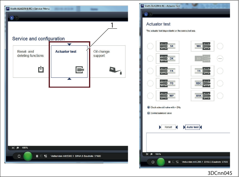
Perform actuator test
Call the button "Actuator test" (1) in ALADIN under the "Service" button.
Use ALADIN to perform an actuator test.
Perform an electrical check on the solenoid valves
DIWA.6: → Perform electric check of DIWA 6 solenoid valves
DIWA.5 → Perform an electric check on the DIWA 5 solenoid valve.
Replace a defective solenoid coil.
Disassemble the control block
Make the pistons of the control blocks run freely.
Perform an electrical check on all solenoid coils again.
Solenoid valve | Pin transm. | Pin transm. | Pin E300.1 | Pin E300.1 |
|---|---|---|---|---|
SK solenoid valve (input clutch) | SK 9 (203) | SKM 25 (3) | SK 3 (203) | SKM 3 (14) |
DK solenoid valve (lockup clutch) | DK 10 (202) | DKM 26 (2) | DK 2 (202) | DKM 13 (2) |
EK solenoid valve (overdrive clutch) | EK 11 (201) | EKM 27 (1) | EK 1 (201) | EKM 12 (1) |
PB solenoid valve (pump brake) | PB 12 (208) | PBM 28 (4) | PB 8 (208) | PBM 15 (4) |
WP solenoid valve (turbine brake) | WP 13 (210) | – | WP 10 (210) | – |
RBK solenoid valve | RBK 14 (204) | RBKM 29 (6) | RBK 4 (204) | RBKM 17 (6) |
RBG solenoid valve | RBG 15 (207) | – | RBG 7 (207) | – |
TB solenoid valve | TB 16 (205) | TBM 30 (5) | TB 5 (205) | TBM 16 (5) |
WR solenoid valve | WR 17 (209) | – | WR 9 (209) | – |
EO solenoid valve | EO 18 (206) | – | EO 6 (206) | – |
Solenoid valve pin assignment
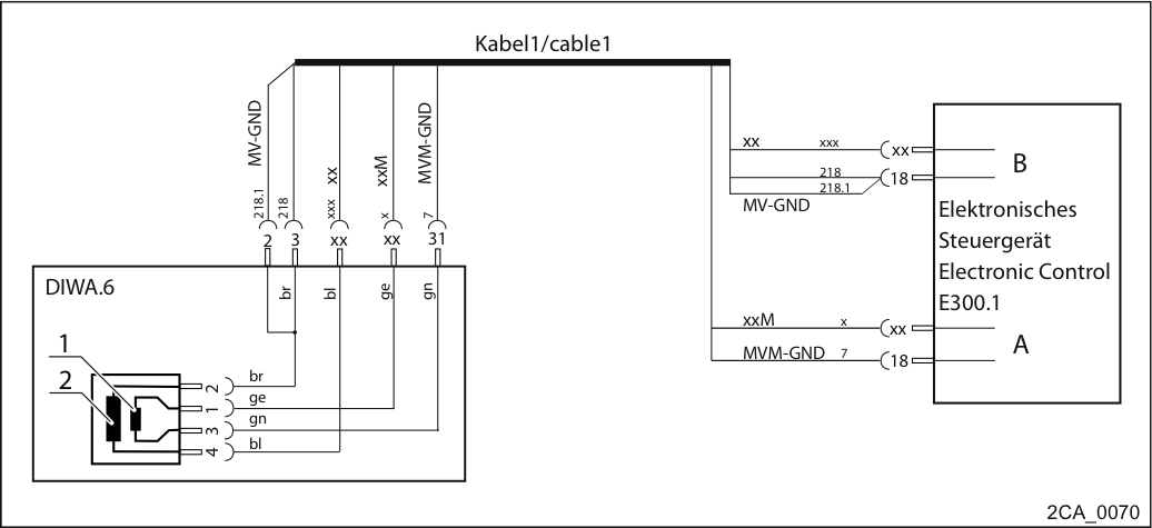
Wiring diagram solenoid valves, general
1. Measurement winding
2. Power winding
Abbreviations:
xx or xxx stands for the pins of the different solenoid valves
(→ 1)
br = brown
ge = yellow
gn = green
bl = blue
Attention! The check may only take place when the cables are deenergized! Therefore, switch off the ignition prior to measuring. For further details, please refer to the wiring diagram (transmission) of the respective vehicle. |  |
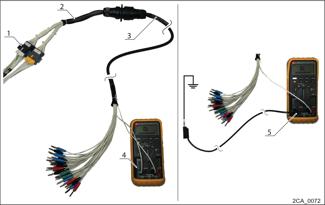
Checking the solenoid valves in front of the controller
Disconnect the connectors A and B from cable 1 on the controller (1).
Connect the adapter (2) and the measuring cable (3). Special tools measuring cable and adapter are required.
Power winding:
Measure the resistance between the connectors EK, DK, SK, RBK, TB, EO, RBG, PB, WR, WP (black) and 2x MV-GND (green) on the measuring cable (4).
Rtarget = 11-20 ohm
Short circuit to ground
Measure the short circuit to ground between the connector EK, DK, SK, RBK, TB, EO, RBG, PB, WR, WP (black) and the vehicle ground (5).
RTarget = ∞ Ω.
Measurement winding
Measure the resistance between the connectors EKM, DKM, SKM, PBM, TBM, RBKM (red) and MVM-GND (green) on the measuring cable (4).
Rtarget = 5-10 ohm.
Short circuit to ground
Measure the short-circuit to ground between the connector EKM, DKM, SKM, PBM, TBM, RBKM (red) and vehicle ground (5).
RTarget = ∞ Ω.
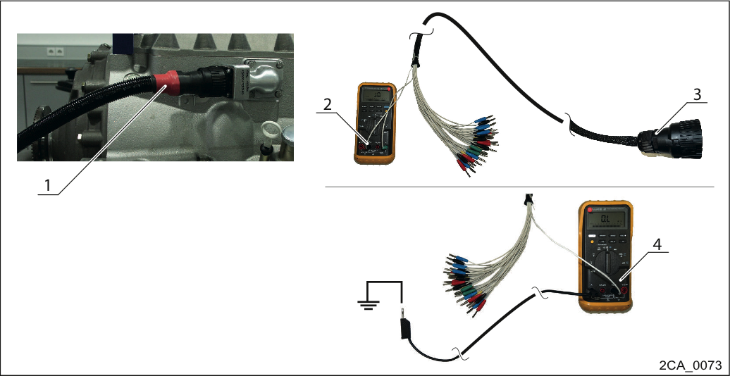
Check the solenoid valves in front of the transmission
Disconnect cable 1 from the wiring harness on the transmission connector (1).
Connect the measuring cable (3) to the transmission connector.
Power winding:
Measure the resistance between connector EK, DK, SK, RBK, TB, EO, RBG, PB, WR, WP (black) and 2x MV-GND (green) on the measuring cable (2).
Rtarget = 11-20 ohm
Short circuit to ground
Measure the short circuit to ground between the connector EK, DK, SK, RBK, TB, EO, RBG, PB, WR, WP (black) and the vehicle ground (4).
RTarget = ∞ Ω.
Measurement winding
Measure the resistance between the connector EKM, DKM, SKM, PBM, TBM, RBKM (red) and the MVM-GND on the measuring cable (green) (2).
Rtarget = 5-10 ohm.
Short circuit to ground
Measure the short circuit to ground between the connector EKM, DKM, SKM, PBM, TBM, RBKM (red) and vehicle ground (4).
RTarget = ∞ Ω.
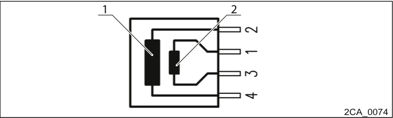
Checking the solenoid valve
1. Power winding
2. Measurement winding
Remove control cover.
Power winding:
Measure the resistance between pin contacts 2 and 4 on the tab plug of the solenoid valve.
Rtarget = 11±0.7 Ω.
Short circuit to ground
Measure the short circuit to ground between pin contacts 2 or 4 on the tab plug of the solenoid valve against vehicle ground.
RTarget = ∞ Ω.
Measurement winding
Measure the short circuit to ground between pin contacts 1 and 3 on the tab plug of the solenoid valve.
Rtarget = 5.2±0.3 Ω
Short circuit to ground
Measure the short circuit to ground between the pin contacts 1 or 3 on the tab plug of the solenoid valve against vehicle ground.
RTarget = ∞ Ω.
Wiring diagram, solenoid valves DIWA.5
1. Measurement winding
2. Power winding
Abbreviations:
br = brown
ge = yellow
gn = green
bl = blue
Attention! The check may only take place when the cables are deenergized! Therefore, switch off the ignition prior to measuring. For further details, please refer to the wiring diagram (transmission) of the respective vehicle. | |
Checking the solenoid valves in front of the controller
Disconnect the connectors A and B from cable 1 on the controller (1).
Connect the adapter (2) and the measuring cable (3). Special tools measuring cable and adapter are required.
Power winding:
Measure the resistance between the connectors EK, DK, SK, RBK, TB, RBG, PB, WR, WP (black) and 2x MV-GND (green) on the measuring cable (4).
Rtarget = 11-20 ohm
Short circuit to ground
Measure the short circuit to ground between the connector EK, DK, SK, RBK, TB, RBG, PB, WR, WP (black) and vehicle ground (5).
RTarget = ∞ Ω.
Measurement winding
Measure the resistance between the connectors EKM, DKM, SKM, PBM, TBM, RBKM (red) and MVM-GND (green) on the measuring cable (4).
Rtarget = 5-10 ohm.
Short circuit to ground
Measure the short-circuit to ground between the connector EKM, DKM, SKM, PBM, TBM, RBKM (red) and vehicle ground (5).
RTarget = ∞ Ω.
Check the solenoid valves in front of the transmission
Disconnect cable 1 from the wiring harness on the transmission connector (1).
Connect the measuring cable (3) to the transmission connector.
Power winding:
Measure the resistance between connector EK, DK, SK, RBK, TB, EO, RBG, PB, WR, WP (black) and 2x MV-GND (green) on the measuring cable (2).
Rtarget = 11-20 ohm
Short circuit to ground
Measure the short circuit to ground between the connector EK, DK, SK, RBK, TB, EO, RBG, PB, WR, WP (black) and the vehicle ground (4).
RTarget = ∞ Ω.
Measurement winding
Measure the resistance between the connector EKM, DKM, SKM, PBM, TBM, RBKM (red) and the MVM-GND on the measuring cable (green) (2).
Rtarget = 5-10 ohm.
Short circuit to ground
Measure the short circuit to ground between the connector EKM, DKM, SKM, PBM, TBM, RBKM (red) and vehicle ground (4).
RTarget = ∞ Ω.
Checking the solenoid valve
1. Power winding
2. Measurement winding
Remove control cover.
Power winding:
Measure the resistance between pin contacts 2 and 4 on the tab plug of the solenoid valve.
Rtarget = 11±0.7 Ω.
Short circuit to ground
Measure the short circuit to ground between pin contacts 2 or 4 on the tab plug of the solenoid valve against vehicle ground.
RTarget = ∞ Ω.
Measurement winding
Measure the short circuit to ground between pin contacts 1 and 3 on the tab plug of the solenoid valve.
Rtarget = 5.2±0.3 Ω
Short circuit to ground
Measure the short circuit to ground between the pin contacts 1 or 3 on the tab plug of the solenoid valve against vehicle ground.
RTarget = ∞ Ω.
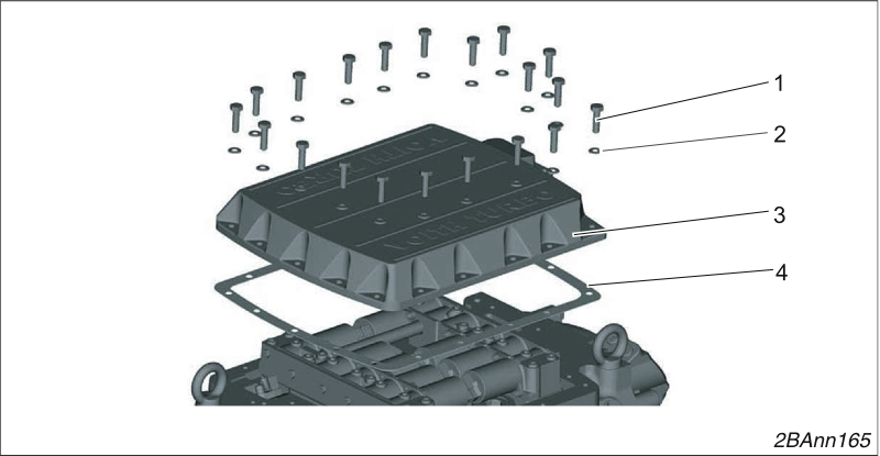
Removing the one-piece control block cover
Loosen 20 screws (1) and remove them with their washers (2).
Remove the cover (3).
Remove the seal (4).
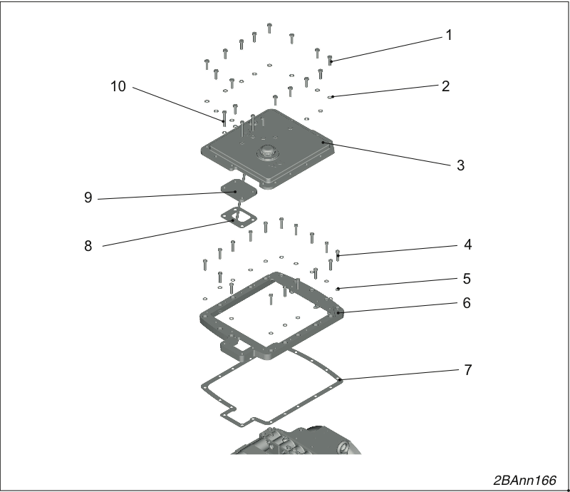
Remove the two-piece control block cover.
Loosen 13 screws (1) and remove them with their washers (2).
Remove the cover (3).
Remove the cover (9).
Remove the seal (8).
Loosen 13 screws (4) and remove them with their washers (5).
Remove the frame (6).
Remove the seal (7).
Installing the control block cover
Insert the new seal (4).
The seal must be free of grease when you install it.
Screw the control block cover (3) tight using 20 hexagon bolts M8 x 30 - 8.8 (1) and washers B 8.4 (2).
Tightening torque 23 Nm.
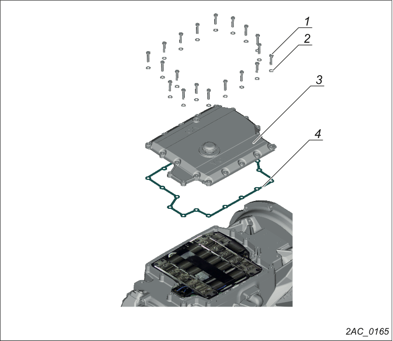
Removing the control block cover
Loosen 20 bolts (1) and remove them with 20 washers (2).
Remove the control block cover (3).
Remove the seal (4).
Installing the control block cover
Insert the new seal (4).
The seal must be free of grease when you install it.
Screw the control block cover (3) tight using 20 hexagon bolts M8 x 30 - 8.8 (1) and washers B 8.4 (2).
Tightening torque 23 Nm.
Order number H68.1535xx
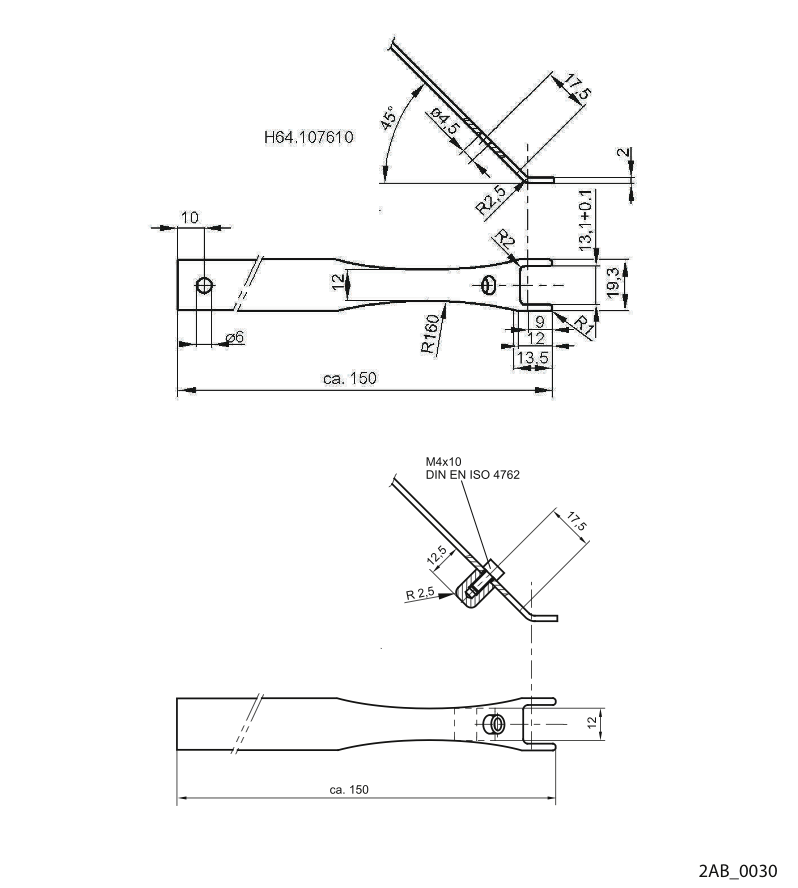
Tool for loosening the cable connectors from the solenoid coils
Order number 150.000145xx
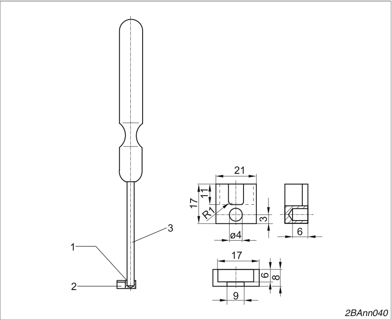
Tool for plugging the cable connectors into the solenoid coils
1. Hard-soldered
2. Insert for assembly tool
Order number 150.000144xx
3. Screwdriver DIN 5265-C-A 0,
8x4, tip removed
In the future, the modified cable guard of the DIWA.6 transmission will be used in DIWA.5 transmissions. If the cable guard in a DIWA.5 transmission has to be replaced, then only the new version of the cable guard is available as a spare part. If the cable guard has to be replaced, then the new version of the cable tray must also be used since only the new versions or the previous versions can be installed together. A mixed installation is not possible. | |
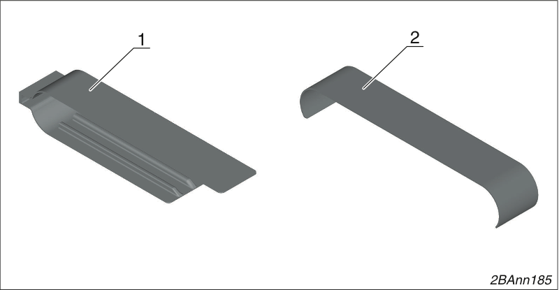
Cable guard
1. Previous version
2. New version
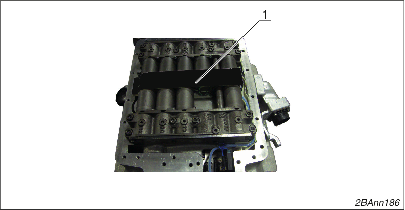
Remove the cable guard
Remove the cable guard (1)
NOTICE
The connection between the plug and cable can be damaged.
To loosen the cable connectors from the solenoid coils, use the special tool.
Never pull on the cables.
Removing control blocks
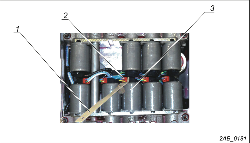
Pull off cable plug (1) from the solenoid coils.
Use the special tool (→ 1).
Removing control blocks
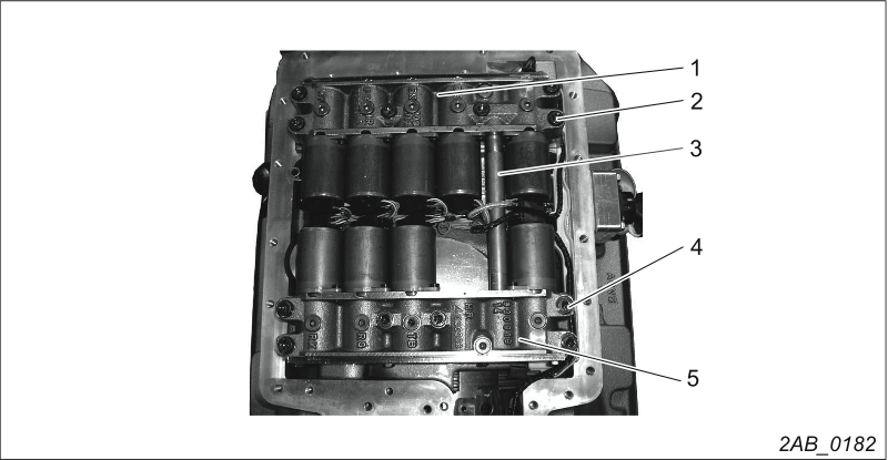
Loosen and remove the 12 socket head screws M8x50 (2).
Remove the spring washers 8 (12x) underneath these.
Remove control blocks (1 and 4).
Pull out connecting tube (3).
Take apart the input-side control block
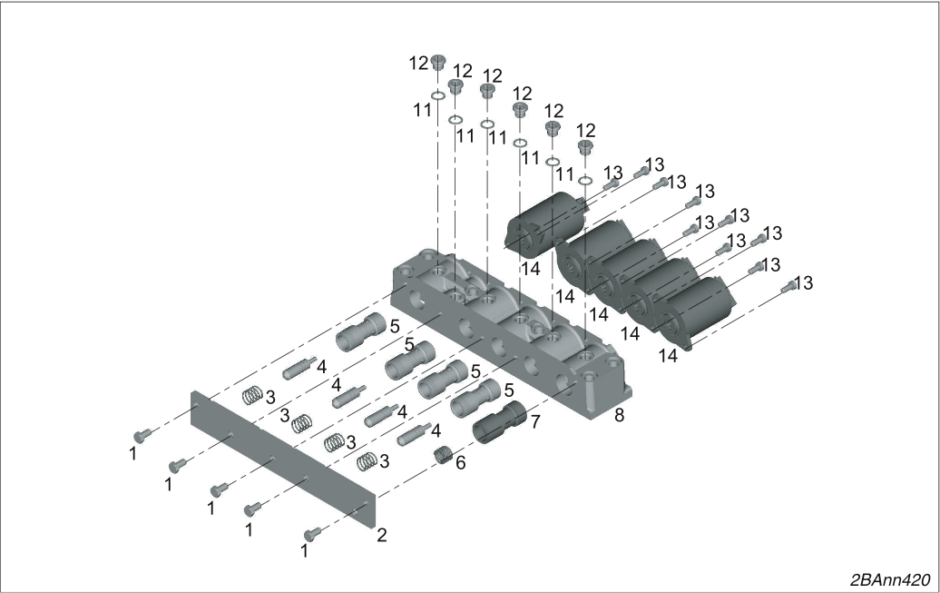
Release 5 hexagon bolts (1) and remove cover (2).
Loosen all screw plugs M10 (12) and remove them with the sealing rings (11).
Otherwise, the pistons cannot be dismantled.
Dismount the following parts from the housing (8):
4 pistons (5)
4 control pins (4)
4 pressure springs (3)
Pistons (7)
Pressure spring (6)
Loosen 10 socket head screws M 5 x 20 – CV84 (13) and remove
5 solenoid coils (14).
Dismounting the output-side control block
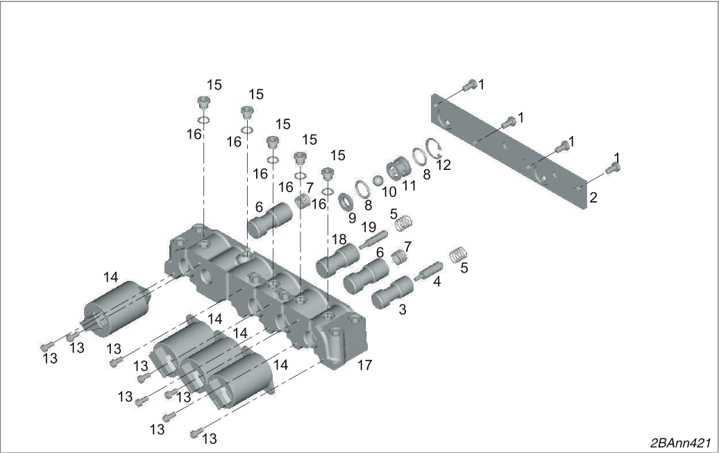
Release 4 hexagon bolts (1) and remove cover (2).
Loosen all screw plugs M10 (15) and remove them with the sealing rings (16).
Otherwise, the pistons cannot be dismantled.
Dismount the following parts from the housing (17):
Pistons (3, 18)
Control pin (4, 19)
2 pressure springs (5)
2 pistons (6)
2 pressure springs (7)
Dismount the insert (9), 2 O-rings (8), ball (10), valve body (11) and locking ring (12).
Loosen the 8 socket head screws M 5 x 20 (13) and dismount 4 solenoid coils (14).
Check the valves for smooth running.
If necessary, make the valves run smoothly (e.g. polish, hone...) or replace them.
NOTICE
Risk of mounting the pistons incorrectly!
If the pistons are mounted incorrectly, transmission malfunctions may occur during operation.
Make sure that spools are mounted in the correct position and run smoothly.
Assembling the input side (drive side) control block
Use 10 socket head screws M 5 x 12 - CV84 (13) to screw the 5 solenoid coils (14) tight.
Tightening torque 5 Nm.
The connections must be on top.
Mount the following parts in the housing (8) again:
4 pistons (5)
4 control pins (4)
4 pressure springs (3)
Pistons (7)
Pressure spring (6)
Screw the cover (2) tight using 5 hexagon bolts (1) M6 x 12 - 8.8.
Tightening torque 9 Nm.
Screw in 5 screw plugs WP M10 x 1 (12) with sealing rings (11).
Tightening torque 15 Nm.
Assembling the output-side control block
Use 8 socket head screws M 5 x 12 - CV84 (13) to screw the 4 solenoid coils (14) tight.
Tightening torque 5 Nm.
The connections must be on top.
Mount the following parts in the housing (18) again:
Pistons (3, 18)
Control pin (4, 19)
2 pressure springs (5)
2 pistons (6)
2 pressure springs (7)
Mount the insert (9), 2 O-rings (8), ball (10), valve body (11) and locking ring (12).
Screw the cover (2) tight using 4 hexagon bolts M6 x 12 - 8.8 (1).
Tightening torque 9 Nm.
Screw in 5 screw plugs WP M10 x 1 (15) with sealing rings (16).
Tightening torque 15 Nm.
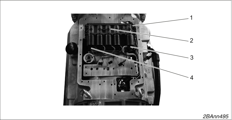
Mounting control blocks
Fix the control block (2) with 6 socket head screws M8 x 50 (1).
Plug 5 cable connectors (4) into the solenoid coils using the special tool (→ 1).
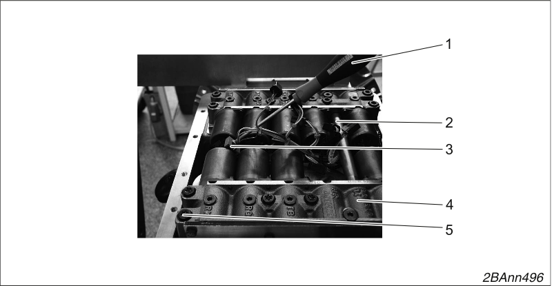
Mounting control blocks
Use a special tool (1) (→ 1) to insert the cable plugs (3) into the
solenoid coils.
Mount the connecting tube (2) with new O-rings 12 x 2.
Fix the control block (4) with 6 socket head screws M8 x 50 (5).
Tighten 12 socket head screws M8 x 50.
Tightening torque 20 Nm.
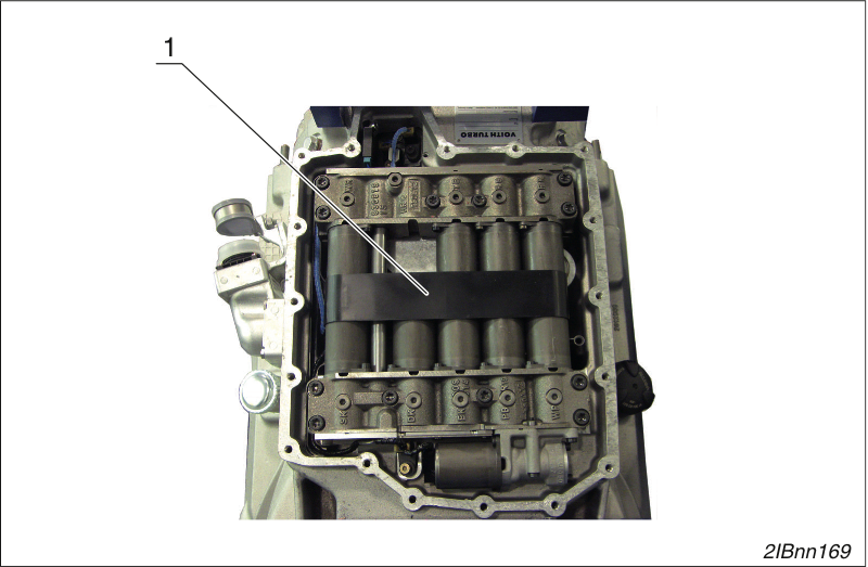
Remove the cable guard
Remove the cable guard (1)
NOTICE
The connection between the plug and cable can be damaged.
When unplugging the cable connectors → 1(1), the contacts between the cable connectors → 1/(1) and cables → 1/(2) can be damaged.
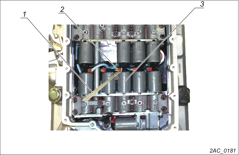
Unplugging the cable connectors
Unplug cable connector (2) from the solenoid coil (3).
Use special tool (1) (→ 1).
Unplug all cable connectors from all solenoid coils.
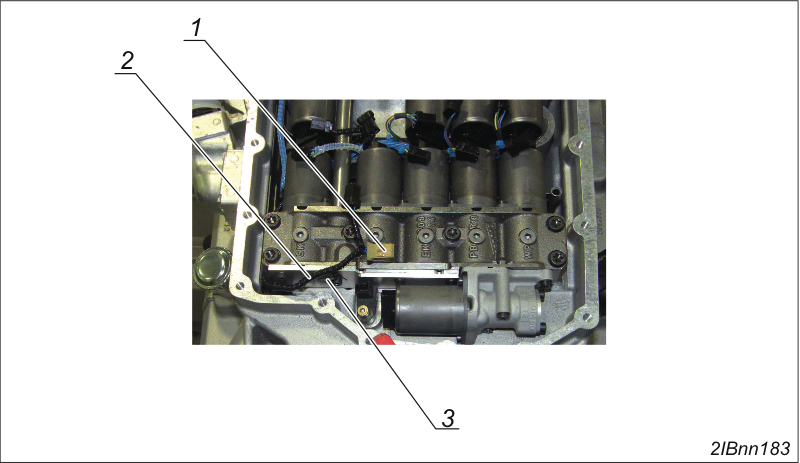
All cable connectors on the solenoid coils unplugged
Unplug connectors from the N1 sensor (1).
Carefully pull line (2) out of the holder (3).

Unplugging the cable harness
Unplug connector (1) from the N2 sensor.
Unplug connector (2) from the N3 sensor.
Unplug connector (3) from the IM.
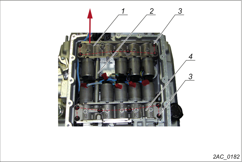
Removing control blocks
Loosen and remove the 12 socket head screws M8 x 50 (3).
Remove the spring washers 8 (12x) underneath these.
Pull the control block (1) carefully in the direction of the output until the connecting tube (2) comes out of the control block (1).
Carefully lift out the control block (1).
Pull out the connector tube.
Carefully lift out the control block (4).
Take apart the control blocks (→ Taking apart the control blocks.).
Check valves (→ Checking valves).
Assemble the control blocks (→ Assembling the control blocks).
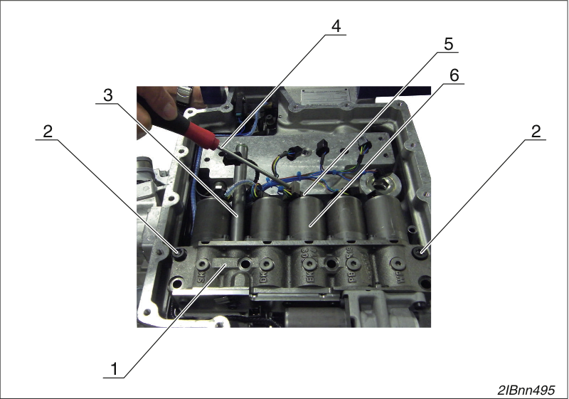
Mounting control blocks
Fix the control block (1) with 2 socket head screws M8 x 50 (2).
Install the connecting tube (3) with two new O-rings 12 x 2.
Plug the cable connector (4) into the solenoid coils (5) with the special tool (3) (→ 1).
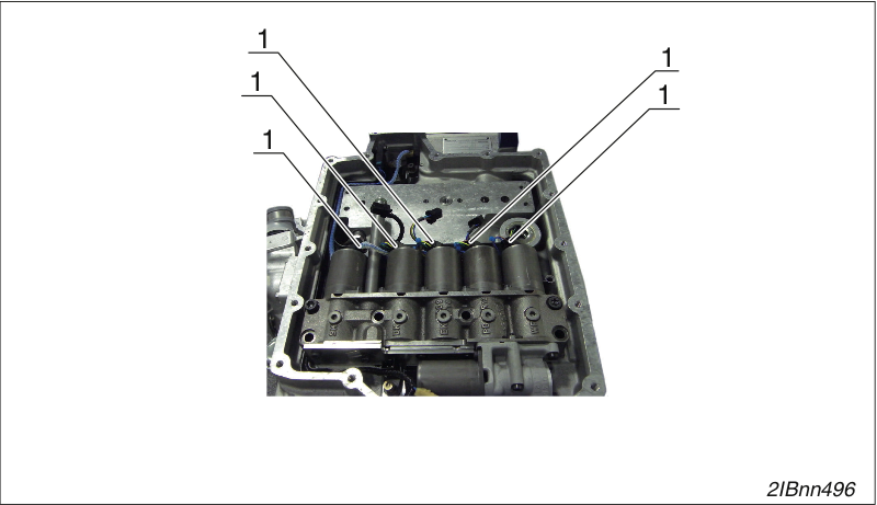
Mounting control blocks
Plug in all six cable connectors (1).
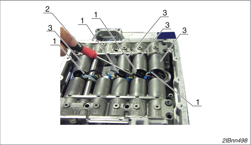
Mounting control blocks
Plug four cable connectors (1) into the solenoid coils (3) using the special tool (2) (→ 1).
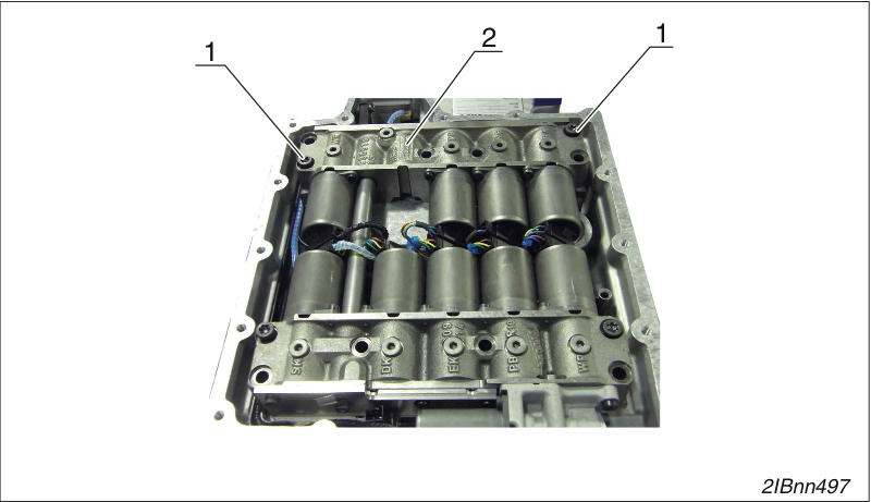
Mounting control blocks
Fix the control block (2) with two socket head screws M8 x 50 (1).
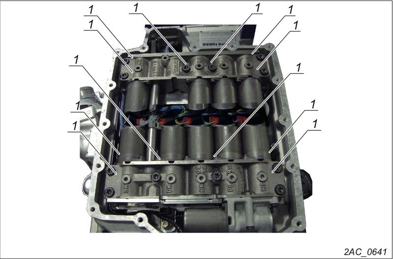
Mounting control blocks
Tighten 12 socket head screws M8 x 50 (1).
Tightening torque 20 Nm.
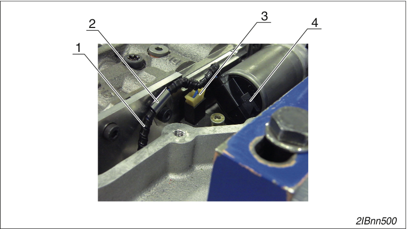
Inserting the cable harness
Insert the cable (1) into the holder (2).
Insert the plug for the speed sensor N1 (3).
Plug in the connector on the EO valve (4) with the auxiliary tool (→ 1).
Mounting control blocks
Mount the cable guard (1).
Order number 150.002484xx.
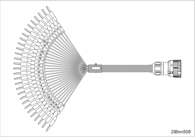
Measuring cable
Cable colors | Cable colors | |
|---|---|---|
9 x black = power coils EK,DK,SK, etc… | including | 2 x green = MV-GND (ground) |
6 x red = measuring coils EKM,DKM,SKM, etc…. | including | 1 x green = MVM-GND (ground) |
6 x blue = speed sensors N1,N2,N3 | ||
3 x yellow = T-CONV, T-SUMP, OIL-LVL | including | 1 x green = S-GND (ground) |
The corresponding designation can be found on each cable.
The task of the measuring cable is to provide the service technician with a tool that enables him to check a defective electric/electronic component on the transmission and to systematically find the fault location.
Order number 150.004143xx.
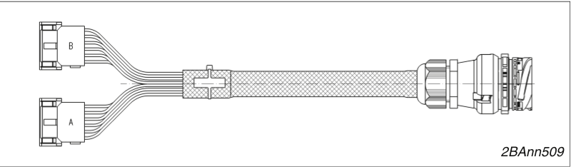
Adapter for measuring cable
This adapter is used to measure the electric/electronic components starting from the controller together with cable 1 using the measuring cable.