
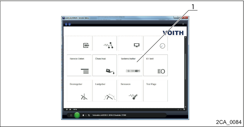
Diagnosing the pushbutton selector
Call the ALADIN monitor (1) to diagnose the pushbutton selector.
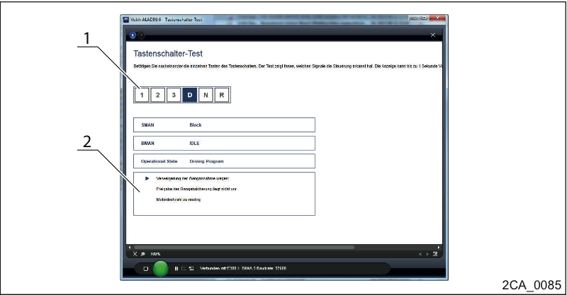
Diagnosing the pushbutton selector
Press all buttons of the pushbutton selector one after the other (1).
Observe the message in ALADIN (2).
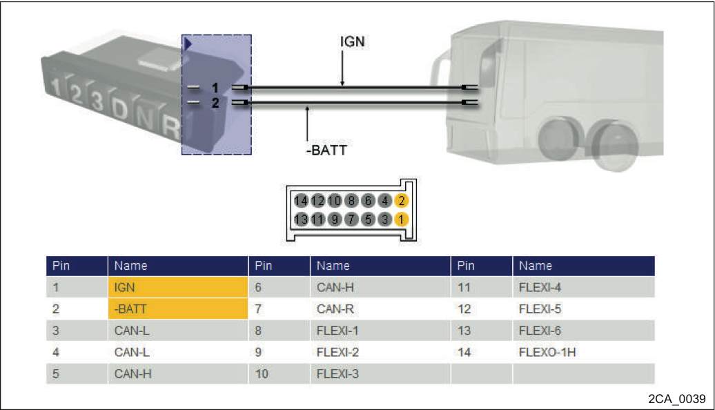
Cable connection and pin assignment of pushbutton selector
Checking according to the wiring diagram.
Check voltage difference between the pushbutton selector and the transmission controller.
The operating voltage difference measured against the respective ground potential of the controller must not exceed 5V.
Check plug connection.
Check the wiring if necessary.
Possibly replace the pushbutton selector or the ECU.
Controller interfaces to the pushbutton selector.
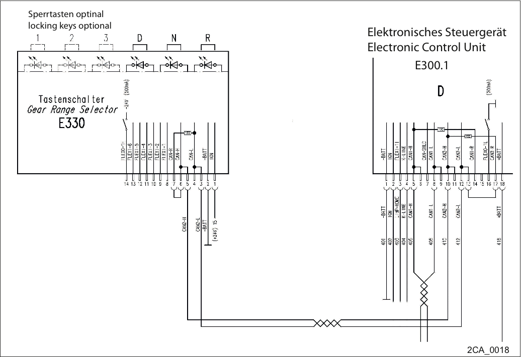
Wiring diagram – Controller interface to pushbutton selector
There are various versions of the wiring diagram for the pushbutton selector
All pushbutton selector variants have a starting lock, i.e. the engine can only be started if no button has been pressed (neutral position).
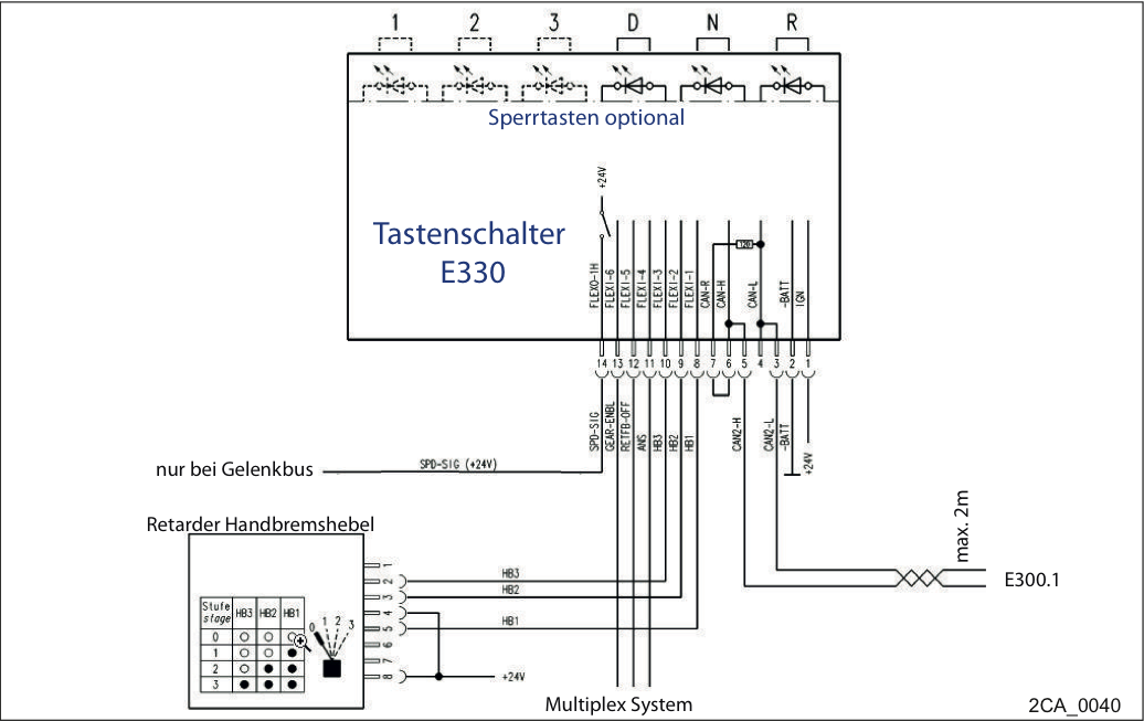
Wiring diagram pushbutton selector – E300.1 Wiring example 1
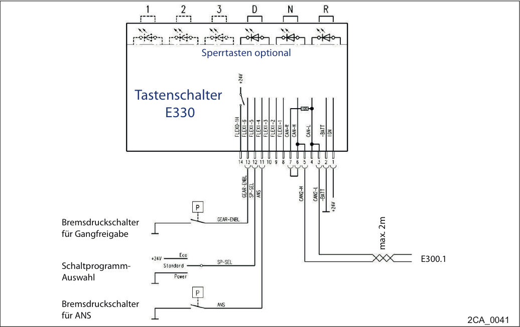
Wiring diagram pushbutton selector – E300.1 Wiring example 2
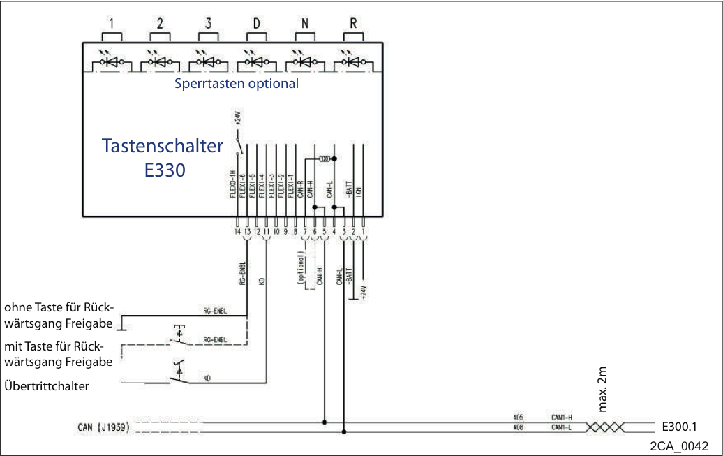
Wiring diagram pushbutton selector – E300.1 Wiring example 3
If the defective component cannot be clearly identified, you should try to reproduce the fault:
Reinstall the component in the vehicle
Test function
Read out the ALADIN monitors
After the fault has been eliminated, the following steps have to be carried out
Perform a test drive (→ ) with a function check.
Read out the fault memory
Check transmission for leaks
Perform a final visual inspection
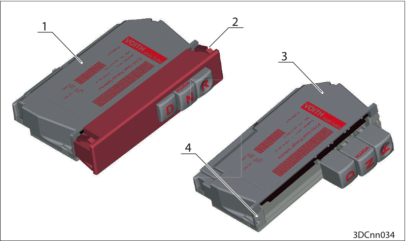
Replace pushbutton selector
1. Pushbutton selector version 1
2. Retaining clamps on the aperture
3. Pushbutton selector version 2
4. Fitting on the instrument panel
Press the pushbutton selector with the aperture out from the rear (behind the instrument panel).
or
Press the clips on the aperture (2) together and push the pushbutton selector out.
Pull out the pushbutton selector.
Disconnect the cabling.
Install the new pushbutton selector in reverse order.
Remove the aperture on the instrument panel.
Remove the two fastening screws (4) on the pushbutton selector.
Pull out the pushbutton selector.
Disconnect the cabling.
Install the new pushbutton selector in reverse order.