| ||||||||||||||||||
| ||||||||||||||||||
Description
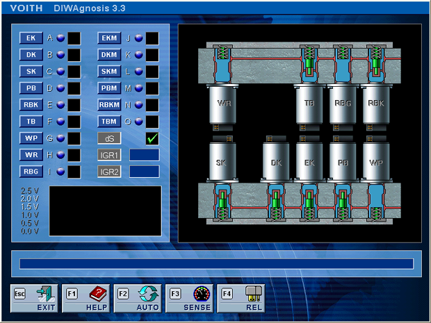
What is the purpose of this function? The diagnostics function allows you to individually control all operator and display elements, such as solenoid valves, relay outputs or warning lights (actuators) in a cyclic manner. Simultaneously to the control action, the software evaluates the status of the controlled output and returns it to the diagnostic systems as the response. If an output is defective, this function therefore allows you to immediately determine whether the output is electrically OK, or the electric circuit is faulty due to short-circuit or cable break. To obtain an audible or visual feedback from the actuators, the outputs are cycled with a low frequency. It is therefore possible to test whether a solenoid valve works smoothly without dismounting or opening the transmission. The test divides into the following subfunctions:
Automatic test - [ F2 ] key An automatic actuator test is started after pressing F2. All actuators are briefly operated (solenoid valves) and/or controlled (measuring coil test) to detect their status. Depending on the diagnostic level, a distinction is made between:
If the control action is defective, the fault memory enables a detailed description of the actuator and its circuit diagram. It also provides a repair instruction. Individual test Each actuator can be controlled separately. For this purpose, click on its button or enter the appropriate identifying letter. The individual test will run until you connect another actuator, exit the menu, or if a condition required for actuator control is no longer met. The individual test is primarily intended to find loose contacts. While the test is running, you may, for example, shake the cable or the plug connection to find a defective contact. If faults occur during the measuring coil test, the relevant test must be restarted. SV supply (dS) This field indicates whether or not solenoid valve supply voltage is present. All actuators are supplied via the dS relay. A defective relay is pointed out by a "red circle" in the window. A "green check mark" means that the SV supply is applied correctly. Solenoid valve measuring coils The solenoid valve measuring coils are shown in the right-hand column (EKM, DKM, SKM, PBM, RBKM and TBM).
ATTENTION! - Measuring coil faults are not written to the fault memory. Solenoid valve power coils The solenoid valve power coils are shown in the left-hand column of the actuator test window (EK, DK, SK, PB, RBK, TB, WP, WR, RBG and TB). The power coils are controlled cyclically. An audible feedback signal allows conclusions as to whether the solenoid valve is mechanically ok or jammed.
SENSE line test If the Sense line is connected to transmission ground, this may result in hard shiftings. The test is based on the fact that in a measuring coil, where the power coil is not under power, no voltage is inducted. The SENSE line test is displayed by a dial instrument whose indicator is steady in the centre position at approx. 1.2 V if the SENSE line is in order. In the event of a fault, the voltage will creep to one of the invalid ranges below 0.8V and/or 1.6V. The test may be retriggered any time by pressing the [ F3 ] key. Relays and variable outputs The relay outputs are controlled cyclically. An audible feedback allows conclusions as to the mechanical condition of the controlled relay.
Fault priority of digital outputs The fault priority of digital outputs can be changed during the test. What to do if a fault is displayed? If the control action is defective, the fault memory (diagnostic function B in main menu) allows you to view a detailed description of the actuator and its circuit diagram. It also provides a repair instruction. Special notes
| ||||||||||||||||||
 © by Voith Turbo GmbH & Co. KG send remarks to markus.zwickel@voith.com (documentation department) | ||||||||||||||||||