DIWA 5 standard connector pin assignments
|
|
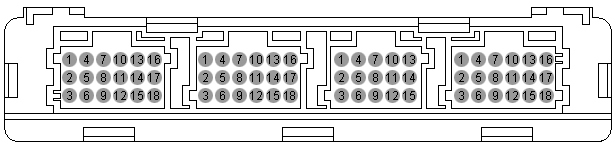
Connector pin assignment of the E300 / E300.1 transmission control unit |
Pin Plug A Plug B Plug C Plug D 1 SHIELD EK FLEXI-1 -BATT 2 TIM+ DK FLEXI-2 (only E300) IGN 3 TIM- SK FLEXI-3 FLEXI-11 4 N1+ RBK FLEXI-4 K-LINE 5 N1- TB FLEXI-5 CAN1-H 6 N2+ -- FLEXI-6 CAN1-H 7 N2- RBG FLEXI-7 CAN-SHIELD 8 N3+ PB FLEXI-8 CAN1-L 9 N3- WR FLEXI-9 CAN1-L 10 -- WP FLEXI-10 CAN2-H 11 -- -- FLEXO-2H CAN2-H 12 EKM FLEXI-12 FLEXO-4H CAN2-L 13 DKM S-GND FLEXO-3H CAN2-L 14 SKM OIL-LVL FLEXO-5L CAN1-R 15 PBM T-SUMP -- -- 16 TBM -- -- FLEXO-1L 17 RBKM T-CONV -- CAN2-R 18 MVM-GND MV-GND -- +BATT
|
|
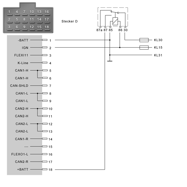
Minimum wiring, transmission control unit: |
|
|
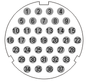
Transmission connector |
Pin Name Pin Name Pin Name 1 S-GND 14 RBK 27 EKM 2 MV-GND 15 RBG 28 PBM 3 MV-GND 16 TB 29 RBKM 4 -- 17 WR 30 TBM 5 T-CONV 18 -- 31 MVM-GND 6 T-SUMP 19 -- 32 N1+ 7 OIL-LVL 20 -- 33 N1- 8 P-DIFF 21 TIM- 34 N2+ 9 SK 22 TIM+ 35 N2- 10 DK 23 -- 36 N3+ 11 EK 24 SHIELD 37 N3- 12 PB 25 SKM 13 WP 26 DKM
|
|
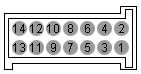
Connector, CAN gear range selector |
Pin Name Pin Name Pin Name 1 IGN 6 CAN-H 11 FLEXI-4 2 -BATT 7 CAN-R 12 FLEXI-5 3 CAN-L 8 FLEXI-1 13 FLEXI-6 4 CAN-L 9 FLEXI-2 14 FLEXO-1H 5 CAN-H 10 FLEXI-3
|
|
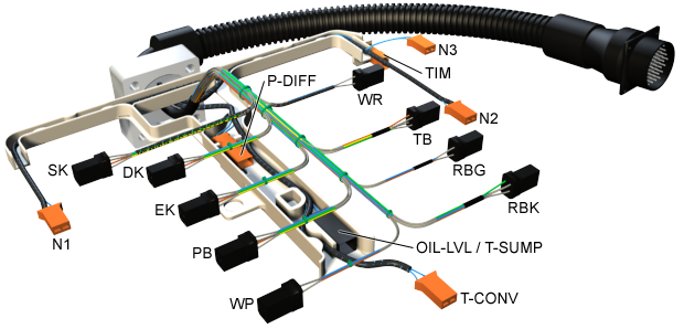
Transmission cable harness |
|
|
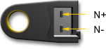
Connector, speed sensors N1, N2, N3 |
Pin Description N+ supply connection N- connection to ground
|
|
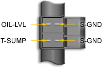
Connector, temperature sensors / oil level sensors T-SUMP T-CONV |
Sensors T-SUMP / T-CONV in connection with the transmission control unit E300
Pin Description 1 connection to ground 2 supply connection
Sensors T-SUMP / OIL-LVL in connection with transmission control unit E300.1 are combined oil level/temperature sensors.
Pin Description S-GND connection to ground OIL-LVL oil level signal S-GND connection to ground T-Sump temperature signal

|
|
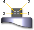
Connector, solenoid valves |
Solenoid valve, controlled: (EK DK SK PB TB RBK)
Pin Description 1 Measuring coil: supply connection 2 Operating coil: connection to ground 3 Measuring coil: connection to ground 4 Operating coil: supply connection Solenoid valves, not controlled:
(WP WR RGB)
Pin Description 1 free 2 Operating coil, connection to ground 3 free 4 Operating coil: supply connection
|
|
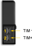
TIM connector |
Pin Description 1 TIM- connection to ground 2 TIM+ supply connection
|
|
K-line interface / level converter for serial interface |
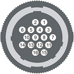
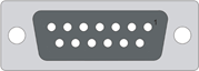
Interface, vehicle side
Pin Description 1 +24V 2 -Batt 3 free 4 free 5 free 6 free 7 free 8 K-line 9 free 10 K-line overridden to pin 8 in the transmission control unit 11 - 16 free
Pin Description 1-4 free 5 -Batt 6 K-line 7 free 8 +24V 9-15 free
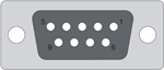
Interface, serial port to PC
Pin Description 1 free 2 K-line 3 L-line 4 free 5 -Batt 6-9 free
|
|
K-line interface / level converter for the USB interface |
Interface, vehicle side
Pin Description 1 +24V 2 -Batt 3 free 4 free 5 free 6 free 7 free 8 K-line 9 free 10 K-line overridden to pin 8 in the transmission control unit 11 - 16 free
Status LEDs at the interface
LED Color Behavior USB orange Lights up if connection is active, flashes during data transmission.
Status green Lights up permanently if device in Boot Loader mode; flashes with 1 Hz if device in Firmware mode.
UBat green Lights up if UBAT (9-30V) is connected. CAN data green Blinks during CAN data transmission. J1708 orange Blinks during J1708 data transmission. K-line green Flashes during data transmission on the K-line
For further information on the K-line interface with a USB interface, please refer to the help for the "HS Light USB" product made by samtec. If you follow this link, please click the "Open" button in the following window "File Download Safety Warning".
|
|
Diagnosis port at the vehicle |
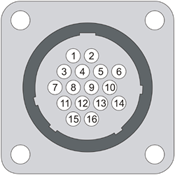
Pin Description 1 +24V 2 -Batt 3 free 4 free 5 free 6 free 7 free 8 K-line 9 free 10 K-line overridden to pin 8 in the transmission control unit 11 - 16 free Several vehicle types require adapter connectors between level converter and vehicle diagnostic port. For further information, please see: Adapter.
 |
Further topics: |
More information on: Adapter
More information on: ALADIN installation
More information on: ALADIN removal
More information on: FAQ
© by Voith Turbo GmbH & Co. KG
send remarks to joachim.ehleiter@voith.com (electronic department)
or r.theilacker@voith.com (electronic department)