Setup - Communication menu
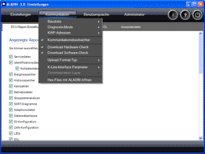
All settings for communication between ALADIN and the control unit are made in the Communication menu.
 |
Note! All settings in the Communication menu are not freely selectable and should only be changed by professionals in exceptional cases! |
 |
How to open the Setup window: |
Click Setup in the main window.

|
|
How to save in the Setup window: |
Click the Exit button in the Setup window. The dialog "Save ALADIN Setup" appears. Click Yes if you want to accept the settings in the Setup. Click No if you want to discard the changes.

|
|
The communication settings |
| The Communication area is divided into several areas. Click the required subject area to get a detailed description. |
|
|
|
||
The Baud rate determines the data transfer rate between ALADIN and the transmission control unit. The default setting is 10,400 Baud and has been marked by the "default" feature in the menu. The activated Baud rate is marked by
 . You can choose between the following Baud rates: . You can choose between the following Baud rates:
|
|
|
Note! This setting is not freely selectable and should only be changed by professionals in exceptional cases. |
|
|
||
The DiagnosticMode decides what diagnostic functions are permitted by the transmission control unit. The DiagnosticMode is independent of your user level and should always be set to "0x86 ECUDeveloperMode". With all other settings, the diagnostic functions might be inoperative. The default setting is "0x86 ECUDeveloperMode" and has been marked by the "default" feature in the menu. The activated DiagnosticMode is marked by
. The following DiagnosticModes are available:
|
|
|
Note! This setting is not freely selectable and should only be changed by professionals in exceptional cases. |
|
|
||
Defines the communication monitoring function between tester and transmission control unit. The activated option is marked by
 .
.If this option is activated, the message window will be opened when the program is started the next time. |
|
|
|
| A variety of control units for different tasks have been installed in modern vehicles. These are, for example, controllers for engine and brakes, as well as the Voith transmission control unit. All control units that observe the KWP2000 (Key Word Protocol) share one central diagnostic port. Similar to a USB connection on the PC, this port is based on an individual serial connection (K-line) between all devices. To ensure that the tester communicates with the correct control unit, every device is assigned an address that is defined in the KWP. | |
|
Note! KWP addresses are not freely selectable and should only be changed by professionals in exceptional cases! |
Option Description KWP tester address The address range between F0h and FDh (hexadecimal) has been reserved for the testers. The default setting is "FA" and has been marked by the "default" feature in the menu. The activated KWP tester address is marked by KWP control unit address The address range between 18h and 1Fh (hexadecimal) has been reserved for transmission control units. The default setting is "18" and has already been stored in ALADIN. You can use the combo box to change the selection.
|
|
|
| These options are used for communication between the tester and the transmission control unit. | |
Option Description Serial interface port / BlueCom Depending on the interface (RS232 / BlueCom) you are using, you can select the corresponding COM port here. When using the USB interface, no entry is required. The USB interface is detected automatically. Upload block mask The upload block mask indicates (in hexadecimal notation) the areas to be read in the memory area as specified in the upload LId. P2 min Minimum time span between a tester request and a response of the transmission control unit, or minimum time span between two responses of the transmission control unit. P2 max Maximum time span between a tester request and a response of the transmission control unit, or maximum time span between two responses of the transmission control unit. P3 min Minimum time span between the end of the response of the transmission control unit and a new tester request. P3 max Maximum time span between the end of the response of the transmission control unit and a new tester request. P4 min Time span between the individual bytes of a tester request. Sample rate Time span between two tester requests. Tester present time Communication between the tester and transmission control unit is active, however, there is no data exchange. This is why the "Tester present" message is sent at defined intervals. The intervals are determined in ms. statusOfDTC This setting refers to reading out the event memory. The following settings are possible: 02: Displays all events that occurred, regardless of whether they are active or inactive.
FA: Only events that are currently active are displayed.
FB: Only events that are currently not active are displayed.
groupOfDiagnosticInformation This parameter controls the entries to be deleted from the event memory. The following settings are possible: FFFFh: The complete event memory is cleared.
xxxxh: The value of the DTC must be entered instead of xxxx to delete an individual entry.
Use timing access If this option has not been activated, the parameters P2 min, P2 max, P3 min, P3 max and P4 min will not be considered. Normal timing is used. Use configuration center ??? Use hardware detection If this function has been activated, hardware is detected automatically. If USB and RS232 interface are connected simultaneously, the USB interface is given priority.
|
|
|
| The download hardware check checks the compatibility of the HEX file to be loaded and the transmission control unit used. If you try to load function software for an E300 transmission control unit into an E300.1 transmission control unit, loading will be terminated. The "Download hardware check" function must be activated as a prerequisite. The activated option is marked by
. |
|
|
|
| The download software check checks the compatibility between two HEX files to be loaded. If, for example, the function software and the dataset are incompatible, loading will be terminated. The "Download software check" function must be activated as a prerequisite. The activated option is marked by
. |
|
|
|
| The upload format type indicates the format of the ECU file or data to be created during an upload. The start and read area of the FRAM is also displayed. | |
| Option | Description | ||
| Normal / extended | "Normal" creates a classic ECU file. "Extended" creates a complete copy of the entire control unit data. Is required for cloning the control unit. |
||
| FRAM checksum check | Defines whether the check sum of the FRAM data is checked. |
|
|
|
| Here you can set whether a hex file is to be opened with ALADIN. To do so, select the menu item. | |
|
|
Further topics: |
More information on: User level
More information on: DiagnosticMode & Baud rate Expert information
More information on: Connect PC to vehicle
More information on: FAQ
More information on: Expert information ALADIN.INI file
© by Voith Turbo GmbH & Co. KG
send remarks to joachim.ehleiter@voith.com (electronic department)
or r.theilacker@voith.com (electronic department)