The TIM
The TIM (Transmission Identification Module) is an extra storage module that is installed in the transmission and not in the transmission control unit. It represents the electronic rating plate of a DIWA transmission and contains information on the transmission design. TIM data is essential for a correct functioning of the transmission software. TIM data is entered when the transmission is manufactured and must never be changed, except for major transmission conversions.
 |
DIWA.5 TIM data overview: |
TM.type
Transmission type. Two transmission types can be selected: 854 and 864.TM.generation
Transmission generation 5 can be selected for DIWA.5.TM.inputAngleDrive
Input angle drive. Not yet available at the moment. 0 can be selected for "None".TM.flange
Input cover / flange. C and D can be selected.TM.differential
Input differential. Differential 3 and 4 can be selected.TM.pumpTyp
Pump type. F, H, K, N, V and X can be selected.TM.turbineTyp
Turbine wheel. T0 and T2 are offered for selection.TM.reverseGear
Reverse gear. R0 and R2 are offered for selection.TM.workingPressure
Operating pressure. 85 can be selected for 8.5 bar and 95 for 9.5 bar.TM.SerialNumber
Transmission serial numberTM.outputAngleDrive
Output angle drive. You can select:
Selection 0 no angle drive provided 1.000 50 W50 (identical to DIWA.3 W18) 1.087 51 W51 (identical to DIWA 3 W21) 0.987 52 W52 (identical to DIWA 3 W22) 1.002 53 W53 0.952 54 W54 1.087
For further information, please see: DIWA Transmission - designs and rating plate.
|
|
Operational principle of the communication with the TIM: |
Communication between ALADIN and the TIM is always done via the transmission control unit and is processed in several steps. If data is to be stored in the TIM, the complete data is first sent from ALADIN to the transmission control unit. In the second step, the transmission control unit forwards the data to the TIM. This write operation takes maximum 10 seconds. Since the TIM is located directly in the transmission, it has been equipped with several safety features such as 'Shut down in case of overtemperature'. Consequently, communication between TIM and transmission control unit cannot be ensured at any time.
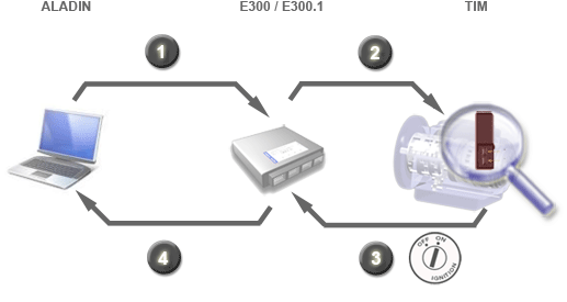
To be able to check whether the write operation in the TIM was successful, the TIM data must be read out to ALADIN again. The transmission control unit reads the TIM data automatically, but only when the system is started. This is why the ignition must be switched OFF and ON again. The current TIM data can now be loaded to ALADIN in the fourth step.
In the event of a faulty TIM, the transmission control unit always uses the TIM data that was last read out from the TIM.
|
|
TIM installation location and connection: |
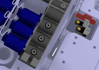
The TIM is installed next to the speed sensors N2 and N3 onto the transmission housing.
The TIM is connected to the transmission control unit with two lines.
TIM connection Transmission control unit connector Transmission connector TIM+ A2 22 TIM- A3 21
|
|
Further topics: |
More information on: TIM data / Write to TIM
More information on: Transmission - designs and rating plate
More information on: Connector pin assignment and electrical transmission connections
More information on: FAQ
© by Voith Turbo GmbH & Co. KG
send remarks to joachim.ehleiter@voith.com (electronic department)
or r.theilacker@voith.com (electronic department)