Display configuration data in the report
 |
The I/O configuration provides information on the vehicle's CAN configuration, shift program configuration and the configuration of the flexible inputs/outputs at the transmission control unit and the gear range selector. |

 |
The I/O configuration with EOL parameterization is displayed for software version E300.1-D5.8.0.0 and higher. The current shift program configuration can be found under LIds. |
 |
Configuration data report contents: |
Digital I/O configuration of the transmission control unit:
The transmission control units of the E300 and E300.1 series are equipped with 12 or 11 flexible (freely selectable) digital inputs and 5 flexible outputs. These are required, e.g., for connecting functionalities of the transmission software to vehicle-specific switches or displays. The use of the flexible inputs/outputs is controlled by the dataset.
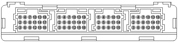
The configured inputs/outputs are displayed together with the connector pin assignment in the ECU report.
Example:
Pin Plug A Plug B Plug C Plug D 1 SHIELD EK FLEXI-1 -BATT 2 TIM+ DK FLEXI-2 (only E300) IGN 3 TIM- SK FLEXI-3 LIMP_HOME 4 N1+ RBK FLEXI-4 K-LINE 5 N1- TB FLEXI-5 CAN1-H 6 N2+ -- FLEXI-6 CAN1-H 7 N2- RBG FLEXI-7 CAN-SHIELD 8 N3+ PB FLEXI-8 CAN1-L 9 N3- WR FLEXI-9 CAN1-L 10 -- WP FLEXI-10 CAN2-H 11 -- -- FLEXO-2H CAN2-H 12 EKM FLEXI-12 FLEXO-4H CAN2-L 13 DKM S-GND FLEXO-3H CAN2-L 14 SKM OIL-LVL FLEXO-5L CAN1-R 15 PBM T-SUMP -- -- 16 TBM -- -- RG_SIG 17 RBKM T-CONV -- CAN2-R 18 MVM-GND MV-GND -- +BATT In the example, the flexible input FLEXI-11, pin3, plug D has been configured for the "Limp_Home" switch. The flexible output FLEXO-1L, pin16, plug D has been configured for the display "RG_SIG" (reverse gear light). For further information, please see: Connector pin assignment.
Digital I/O configuration of the CAN gear range selector:
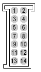
The Voith gear range selector has 6 flexible (freely selectable) inputs and one flexible output. The states of these inputs/outputs are transmitted to or received by the transmission control unit via the CAN bus. The flexible inputs/outputs are required, e.g., for connecting functionalities of the transmission software to vehicle-specific switches or displays. Example:
Pin Name Name Pin2 1 IGN -BATT 2 3 CAN-L CAN-L 4 5 CAN-H CAN-H 6 7 CAN-R SP_SEL 8 9 FLEXI-2 RG_ENBL 10 11 FLEXI-4 FLEXI-5 12 13 FLEXI-6 FLEXO-1H 14 In the example, the flexible input FLEXI-1, pin8, plug D has been configured for the SP_SEL (shift program selector) switch. The flexible input FLEXI-3, pin10 has been configured for the RG_ENBL (additional 'reverse gear enable') switch. For further information, please see: Connector pin assignment.
Digital input is active at...
Every switch can be assigned three different states: switch is closed to supply voltage (+24V), switch is closed to ground (GND) and switch is open (no electrical connection). "Digital input is active" indicates the input signal that activates the configured functionalities in the transmission software. Example:
+24V OPEN GND Digital input LIMP_HOME RG_ENBL SP_SEL In the example, the LIMP_HOME switch is active if the switch is closed to supply voltage or to ground. The "reverse gear enable" switch RG_ENBL is active if the switch is closed to supply voltage. The same applies to the shift program selector switch SP_SEL.
CAN configuration at the transmission control unit port:
The transmission control unit has two separate CAN bus ports CAN1 and CAN2. The possible configurations at the vehicle are:
- CAN1 for vehicle communication and CAN2 for communication with the gear range selector.
- CAN2 for communication with the vehicle and gear range selector, CAN1 not used.
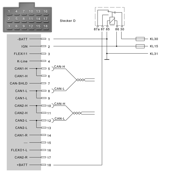
The vehicle configuration is displayed in the ECU report including the minimum wiring of the transmission control unit.
Example:
In the example, CAN1 has been configured for vehicle communication and CAN2 for the gear range selector. The minimum wiring for the operation of the transmission control unit is the supply voltage with -Batt and +Batt and the ignition switched on (IGN).
How to change the configuration of the digital inputs and outputs:
To change the digital inputs and outputs, use the Voith EOL Manager. For further information, please see: Voith EOL.


|
|
How to adjust the report contents: |
In the ALADIN Setup, you can configure what is displayed and how it is displayed in the ECU report. Click Setup > Report in the main window. For further information, please see: Report setup.
|
|
Further topics: |
More information on: Upload
More information on: Setup
More information on: ECU files
More information on: Connector pin assignment
More information on: Shift program configuration
More information on: User level
More information on: SORT
More information on: Dataset
More information on: CAN
More information on: EOL
More information on: LIds
More information on: FAQ
© by Voith Turbo GmbH & Co. KG
send remarks to joachim.ehleiter@voith.com (electronic department)
or r.theilacker@voith.com (electronic department)